
This will be my first real post. Actually, this SU carb rebuild is what prompted me to begin this blog in the first place. A group of guys in California decided to help a friend get her 1964 122S sedan back on the road, and the SUs were near the top of the list of things that needed doing, so they sent them to me.
The following link is to photos of the work being done on the car. The owner, Annette, appears in some of the photos, as does Ben Buja, the guy who appears to be doing most of the work, including the carburetor removal and cleaning:
(http://www.flickr.com/photos/68144590@N00/sets/72157635906118514/)
I was asked to take a few pictures of the carburetor rebuilding process, which I did. Turned out that I took over a hundred pictures. Once I had all those pictures, it seemed the right thing to do to write up an explanation of what was going on, so this is it: my first attempt at blogging. Some of the pictures were real duds or repetitive, so they were pared down to about 87 or so that will be included in this post. My hope here is that I show enough of what I do and how I do it that any interested (and determined) party can do this job himself. I don’t really get all that much fun out of rebuilding carburetors anymore, and it’d be just fine with me if someone else decided he’d like to take over the service.
The primary purpose of this post is to teach and not to sell.
First of all, you should know that my policy** is that carbs should be shipped to me clean. I don’t have good cleaning facilities, and the manual cleaning process can be quite time-consuming, so I don’t want to do it. Sometimes I will, and sometimes I won’t. One guy recently sent me a pair of dirty carbs, and my wife caught me sneaking out to the woods to clean them, so that I could keep the mess out of our new garage. She told me I shouldn’t be doing that, so I mailed them back undone, telling the customer to clean them. He never did send them back, so I guess he didn’t want to clean them, either.
** That was then; this is now (5/27/2016): I now have an ultrasonic cleaner, so I’m much less particular about how clean the carbs are when I receive them. Please dump out the gasoline, and make sure you empty the dashpot oil and wash the dashpots out with carb cleaner or similar, and let them dry out before packing them. The USPS doesn’t like the smell of gasoline or oil soaked boxes. Other than that, you really don’t have to do any cleaning. But… ultimately, I don’t consider myself a carburetor cleaner. I make ’em work; I don’t make ’em pretty. Complaints about cleanliness or appearances will get no sympathy, I’m afraid.
These particular carbs had been pretty nicely cleaned when I received them from the customer. Here’s a picture of them, fresh from the customer:  These carbs were pretty clean, on the outside at least, so I was happy; I don’t care about the inside, I’ll clean that up if I have to, so don’t bother to disassemble your carbs for cleaning before you send them to me.
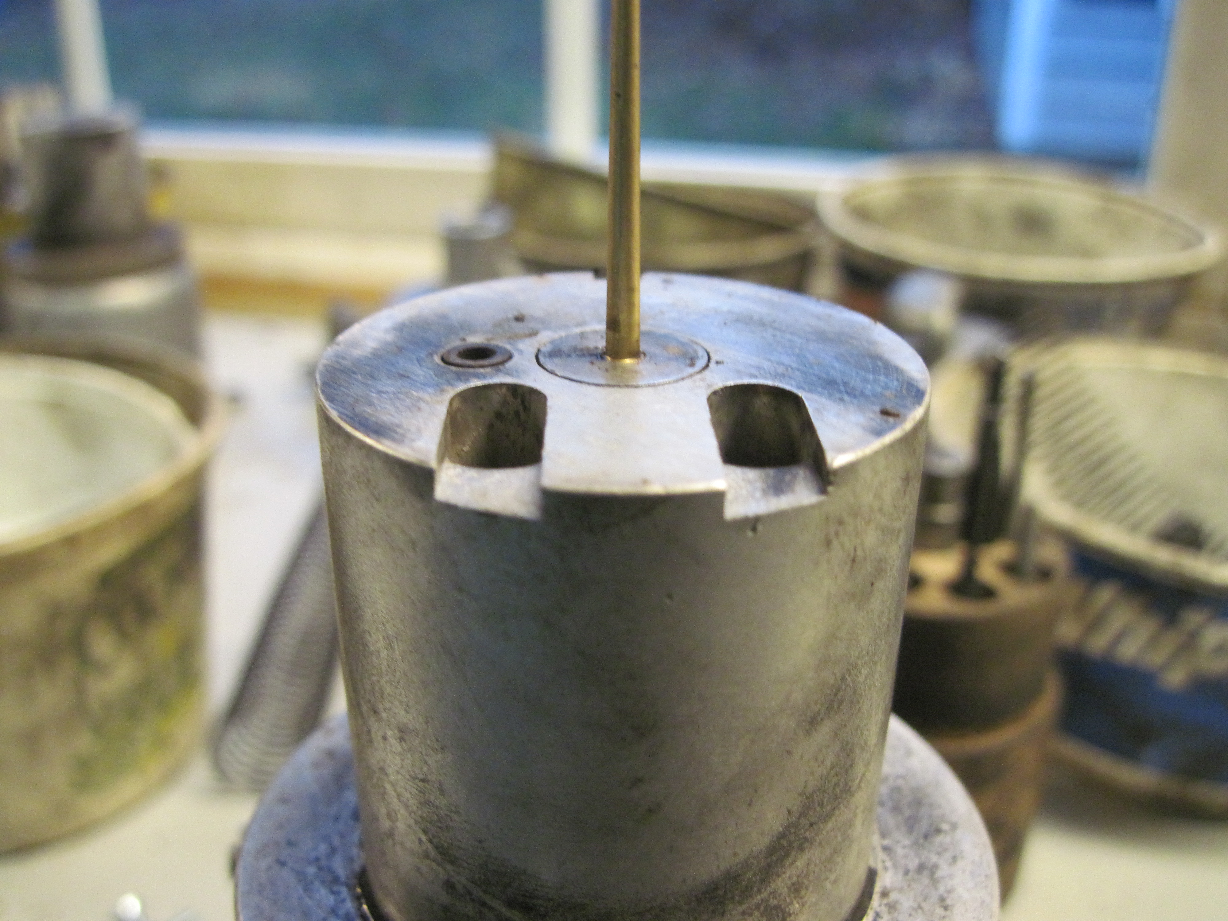
The following picture shows the carbs all torn apart before rebuilding. Unfortunately, it’s out of focus, or my hand shook, so it’s poor quality, but it’s the best I have, so here it is:  Note the Green, Silver, and Red tool near the bottom center of the shot. That is a special tool that I use to check the jets for wear. One end holds a 0.0900″ gauge pin, used for 0.090 jets used on smaller carbs, such as the Type H-4 carbs used on Volvo B16 engines. The other end holds a 0.1000″ gauge for the larger 0.100″ jets used on larger carbs, such as the Type HS-6 carbs used on Volvo B18 and B20 engines. The gauge pins and holders are available from any good industrial supply house. I bought mine from mscdirect.com. This link should get you close: http://www.mscdirect.com/browse/Measuring-Inspecting/Inspecting-Detecting-Testing-Instruments/Go-No-Go-Gages-Accessories?navid=12107665
My gauges are just about exactly the diameter of a brand-new, unworn, jet orifice. If there’s more than a smidgen of clearance around my gauge pin, I replace the jet. Both jets for this pair of carbs were worn a bit and required refurbishing. Note the placement of the nut driver and socket extensions in the photo above. That was done to hold the gauge at an angle, while my hands were occupied using the camera, and show how sloppy the jet hole was.
The sloppy hole isn’t all that obvious above, so here’s a close-up:  Notice how much wobble angle there is between the jet and the gauge pin. I rejected this jet. Fortunately, the customer sent me a third jet, which I was able to salvage. More on this later. Also, notice the unusual (conical brass) fitting on the float bowl end of the tube on that worn jet. I’ll discuss this later, near the end of this post.
Jets don’t wear, provided the jet bearing is properly centered. There are special tools for this job, but don’t bother to buy one; they don’t work. You can’t get a better centering tool than the actual jet and needle pair to be mated to one another. Commercial centering tools can only introduce another layer of inaccuracy into the equation, resulting in alignment that can never be better than using the actual parts, and is often a lot worse. Even when jets get worn, the needles are seldom affected, so it’s an extremely rare occasion when I have to replace a needle. And usually that’s not because they’re worn, but because I couldn’t get them out for inspection without damaging them. Needles have gotten to be rather expensive, so I just don’t replace them unless it’s necessary, and it seldom is.
To remove a stubborn metering needle, often the best approach is to first remove the set screw, then put a bit of PB Blaster in the hole, let it sit a while, then gently tap the needle on the end with a hammer, driving it in farther, after which it will usually come right out.
Here’s a close up of the rear float bowl, cover, and float valve:  This is an original-type float valve, with a steel needle. These original valves work reasonably well, when they’re new, but eventually, the pin gets worn, and they start to leak. Eventually, the leakage rate is high enough that the float bowl will overflow, and that’s not good. This float valve shows a fair amount of wear, probably enough to make it leak occasionally. I never re-install one of these original-type float valves, even if it’s brand-new; there are better parts available. Also, note the excellent condition of the float bowl gasket in the above photo. This one looks as if it has been recently replaced. At any rate, it’s better quality than most aftermarket float bowl gaskets. I re-used this gasket, which is what I usually do when the old gasket is as good as, or even better than, what I can buy brand-new.
The next photo shows the throttle shaft for the rear carburetor:  Now, that throttle shaft is about as badly worn as I’ve ever seen. Usually, carburetors become essentially unusable long before they get worn to this extreme; no wonder the owner sent the carbs for a rebuild. What happens is that, because of the large gap around the throttle shaft, the mixture can’t be set properly, and because of the uneven wear, the throttle shaft comes to rest at random idle positions, so the idle speed is erratic.
The basic problem here is that the original throttle shaft bushings, cast into the aluminum body of the carbs, are brass, the same material as the shafts. It’s never a good idea to use the same material for both a shaft and its bearing because the similar materials tend to micro-weld together as they move, resulting in rapid wear. It is this characteristic of SUs that, more than anything else, gave them their reputation for unreliability. Quite frankly, whoever came up with this design should have known better. He obviously didn’t have any real engineering competence. This design is nothing short of sheer ignorance. That Skinner Union continued to use this design, long after its shortcomings became obvious, is completely inexcusable. I have to blame it on the bean counters, because otherwise I’d have to assume utter incompetence on the part of some Mechanical Engineer.
But, it gets worse. Here’s a shot of the front carb and throttle shaft:  This particular throttle shaft is, almost certainly, the very worst one I’ve ever encountered. It’s worn much more than the rear one and has a groove over 0.040″ deep. Unbelievable that this car was still on the road with wear this extreme. Note how the deepest grooves are quite narrow, with longer, less-worn, portions between them. Those grooves are where the shafts contact the aluminum body of the carbs, and the less-worn parts of the shaft are where it contacts the cast-in brass bushings. So, this seems to go counter to my advice about not using similar materials for shaft and bearing, right? Well, not really. If the brass bushing hadn’t worn so much, the aluminum body of the carburetor would not have been able to cut into the shaft. You must realize that the combined wear depth of the shaft and the brass bushing, between the deep grooves, must be equal to the depth of the deepest groove on the shaft. In other words, the brass bushing inside the carb body must be worn about the same amount as the shaft itself.
The aluminum SU carburetor body has some nice abrasive on it, commonly known as aluminum oxide, which will cut into the soft brass shaft rather nicely, if given the chance. Meanwhile, as the aluminum oxide cuts into the shaft, the aluminum carb body itself doesn’t wear much at all, so if you were to put a new shaft into that old carb body, it would seem fairly tight, and one might think it would be okay to use it without re-bushing. Well, there’s all that bushing wear between the two aluminum portions of the bushing area, and that leaves the shaft unsupported, except where it touches that abrasive carb body, so wear on the new shaft will be rapid. It’s not a good idea to just throw in a new shaft and hope for the best, ’cause it’s not going to work well for very long.
This design is so bad that I’ve actually had one person, who understood just how bad it was, send me a brand-new carburetor so that I could re-bush it before it could self-destruct. An ounce of prevention. My solution to this problem is to install Delrin bushings. Delrin is a DuPont trademark for their acetyl resin plastic. See: http://www.dupont.com/products-and-services/plastics-polymers-resins/thermoplastics/brands/delrin-acetal-resin.html
Actually, I rather doubt if the material I use is DuPont’s, but it’s the same stuff. I did some testing on Delrin, as well as other materials, back in June of 1993. Delrin was the clear winner and seemed to have the right properties of lubricity, dimensional stability, and heat and chemical resistance for the job, so I’ve been using it ever since, with totally satisfactory results. The Delrin bushings seem to reduce wear down to undetectable levels, and they’re dimensionally stable, don’t creep, and don’t fall out. They’re also very easy to install and quite forgiving of a less-than-perfect machining operation. One can be quite sloppy with the installation; the carbs will still work just fine, and the customer will never know the difference. The original, cast in, brass bushings have an outside diameter of about 0.375″. I use a “T” (0.358″) reamer to remove most of the brass bushing so I can install the new Delrin bushing.
Although I originally used a 3/8″ reamer to cut out the brass bushings, I no longer do so. I don’t remove the entire original brass bushing because that often causes problems with off-center cutting, stuff falling out, or bits and pieces being left behind, and a generally poor fit to the new Delrin bushing. Experience taught me to go smaller and avoid all the problems, so that’s why I now use a “T” reamer. My Delrin bushings are machined to give about a 0.010″ interference fit in the “T” reamer hole, so they have an OD of about 0.368-0.372″. The ID is about 9/32″, and they’re a bit over 1/2″ long, about 9/16″. None of these dimensions is particularly crucial; lots of tolerance is acceptable.
To cut out the bushings, I first align the carburetor body to the drill press using a piece of 5/16″ drill rod as an arbor, as shown in the following picture:  The arbor is inserted into the chuck of the drill press, then through both throttle shaft bosses, and the drill press vise is moved until everything lines up nicely. This step requires a bit of care, but the materials and process are forgiving of slight imperfections, so extreme accuracy or special tooling, such as bore indicators, are not necessary. In the above picture, please note that the longer of the two throttle shaft bosses has been placed upward, toward the drill press chuck. The lower one is not visible in the picture, so just take my word for it that the one you see is longer. The reason this should be done will be discussed later.
The arbor was removed from the drill press chuck, and a “T” reamer installed, then held down against the throttle bushing boss, as shown in the next photo:
 The “T” reamer is held down against the carburetor, using the drill press stop; see the next picture. Then, the drill press stop is set for 1/2″ travel, as shown below:
 Note the lower stop nut, visible just above the dial indicator needle, and screwed up against the bottom of the drill press stop, which is used to hold the reamer down against the carburetor body while setting the top stop nut for 1/2″ travel. Note that limiting the hole to 1/2″ depth leaves some of the old bushing in place, thus preserving the inside of the carburetor body and leaving a good (low leakage) fit between the throttle plate and the carburetor body.
The next shot shows the result after reaming out the “top” bushing:
 Note that some of the original brass bushing is left in place, for reasons discussed above.
Next, tap the “top” bushing into place:
 I’m using a special, short, stepped drift, with a small diameter that fits loosely inside the bushing. This makes it easy to install the Delrin bushing without damage.
Here’s the bushing after installation:
 The bushing is intentionally made a bit longer than 1/2″ just to make sure it’s long enough.
Next, I use a coarse file to trim the Delrin bushing to proper length:

And here’s the result:

Next, flip the carburetor body over, insert the 5/16″ drill rod (arbor) into the drill chuck, and align the top (and bottom) holes with the drill press chuck:
 Note that the drill rod is inserted through the original brass “bottom” bushing (which is now at the top) and into the short piece of undisturbed “top” bushing (which is now at the bottom). As mentioned earlier, this is why the longer bushing boss was originally placed at the top, so that there would be enough “meat” left at the inside of the bore to catch the end of the arbor and ensure proper alignment of the chuck and top and bottom bushings.
Here’s a shot of the “T” reamer installed in the chuck, just before setting the drill press stops and reaming the “bottom” (now at the top) bushing:

Next step, crank the “T” reamer down against the carb body and lock it in place using the lower drill press stop nut:
 Now, set the upper drill press stop nut for 1/2″ travel, as shown previously for the top bushing.
Here’s the drill press stop after setting both stop nuts and then reaming the “bottom” bushing to 1/2″ depth:
 Note that the top stop nut is now against the drill press stop, while the bottom stop nut has moved downward by 1/2″ to give the proper reamed depth for the new bushing.
The next shot shows the “bottom” bushing after reaming:
 Note, once again, that some of the original brass bushing is left behind.
Now, using the special drift, tap in the “bottom” Delrin bushing:

Here it is, fully installed, with the drift still in place:

Now, file the “bottom” bushing to length:

Now, install an extra-long 19/64″ drill (available from places like MSC) into the drill chuck:

Below, the drill is used to drill down through both bushings, ensuring near-perfect alignment of the two throttle shaft holes:
 Some imperfections in the bushing alignment usually exist at this point, but they should be small enough to not cause problems; the drill makes a pretty straight pair of holes.
Next, insert a 5/16″ straight-fluted reamer into the drill chuck:

Then, ream right down through both Delrin bushings:
 The reamer tends to follow the holes, so if there is any misalignment, it’s likely to still be there. It’s rare for there to be a “perfect” fit to the throttle shaft at this point.
So, use a hand-reamer to finish the job and make sure that the bushings are proper size and perfectly aligned:
 The hand reamer is inserted through one bushing, without turning or cutting, then used to finish cut the second hole so that it aligns perfectly with the first hole.
Now, turn the carburetor body around and do the same thing to the other bushing so that both are now “perfectly” straight, aligned, and proper size:
 The finished holes are 5/16″ (0.3125″) exactly, and leave very little clearance for the 0.310″ throttle shaft. Sometimes a bit of tweaking is required. I have some slightly larger reamers available, just in case. But I almost never have to use them.
Below, I have just removed the two throttle shaft pins, one from each shaft:
 Note the two different drift punches, a short one for getting the pin started, and a long one for finishing the job. I can’t tell you how many long punches I broke over the years, trying to start stubborn pins, before I said: “Hey, this is stupid”, and started using one of those short, broken, punches to get the pins started and on their way out. I haven’t broken a single punch since that time.
Here, I have a new shaft installed in the front carburetor, the throttle plate in place, and the linkage fork properly positioned:

Next, use a drop of Loctite 290 (green, wicking grade) to lock the linkage fork in position for drilling:
 Notice how badly worn the linkage fork is, this pair being by far the worst-worn ones I’ve ever seen. I flipped these ones over and put them on the opposite carbs, they were so bad.
Also, notice that the linkage fork is aligned with the axis of the carburetor bore, parallel to the numbered label on the side of the carburetor body. The Loctite is used to ensure that the fork stays in that position until it has been drilled and the pin hammered into place.
Here’s a shot of the rear carburetor with throttle plate and linkage fork in place:
 The piece of paper came with the new shaft. It shows contact information for my supplier, Joe Curto, http://joecurto.com/ who makes these shafts himself. Joe is the source for the very best SU parts. No one makes or sells better stuff.
The paper shows some generic instructions for SU shafts, both for HS-6s, like these, and other types where you have to cut the shafts to their final length yourself. Note three things:
1. Joe recommends using a 1/8″ drill for the linkage forks and installing them with roll pins.
2. Joe also makes some oversize shafts that require a larger “P” reamer.
3. I don’t use either of the above. I like using the original size pins, which strike me as better than the roll pins. And I see no good reason to cheap out and use an oversize shaft. There’s precious little time or money to be saved, and the oversize shaft will just fail again in fairly short order, whereas the Delrin bushings are, essentially, permanent. And rebuilding a carburetor that has been “butchered” with an oversize shaft is really an unpleasant task. I can do it, but I don’t like to. Tricks of the trade are required, and the final result is likely to be a bit substandard due to the larger holes around the throttle shaft, which will introduce extra leakage. Then, there’s also the larger holes in the throttle shaft hardware, such as the linkage forks, which must be re-bushed back down to standard size. Please, never allow anyone to install an oversize shaft in your SU carburetor.
Here’s the new shaft, end fork held in place with Loctite 290, and held in my drill press vise, ready for drilling:
 Since the original shafts all seem to have been pretty much randomly drilled, probably by hand, there seems to be no good way to make special tooling to hold these shafts at the proper rotational angle for drilling, so I just line ’em up by eye and drill away. I rarely miss, at least not by much.
Next, drill the shaft for installation of the pin. With luck, neither of the two original holes in the linkage fork gets drilled any larger than it already is:

I’m using a No. 32 (0.116″) drill. Occasionally, I might use a larger No. 31 (0.120″) drill, but the smaller drill is almost always better. Notice how badly worn the linkage fork is. This fork was originally on the rear carburetor, but it’s now being installed on the front carburetor because of that extreme wear.
Below, I have placed the linkage pin in place but have not yet hammered it home:

Now, it’s been hammered into place:

Now I move on to refurbishing the “spare” jet to replace the badly worn one that was in the front carb:
 A worn rear jet is at the top of the photo, and the spare front jet that the customer sent me is shown below. Notice how much longer the lower one is. That’s because it’s been pulled apart and needs to be put back together.
Getting ready to remove the locking ring from that spare jet:
 Normally, I would be holding that 7/16″ wrench while I hit it with the hammer to knock the locking ring off, but I didn’t have enough hands, so you’ll just have to pretend I’m holding the wrench. Notice that the jet is being held in the vise with a pair of wooden “soft jaws” to prevent damage to the hollow jet.
Here I have the locking ring removed:

Now, see the worn and spare jets side by side again:
 Notice that the “spare” jet is now not much longer than the worn jet; that’s because I’ve squeezed it back together using the vise, leaving it the same length or just a bit longer than the worn one, or at least I hope so.
Next, place a 1/4″ drive deep socket over the jet:

And squeeze it in the vise to seat the locking ring:

Next, compare the worn and “spare” jet lengths:
 The spare one is just a bit longer, as I had intended.
So, place it in the vise and squeeze it back together, just a little bit:

And compare them again:
 Perfect.
Now I go to work on the plastic jet tube. First, pry the locking ring off the jet base:

Below are most of the pieces that make up a jet assembly:
 I even have a couple of extra pieces shown. There are actually four of the brass tube end reinforcement pieces in the picture. Two in plain sight, one mostly hidden in the jet base, and another hidden in the right end of the tube. I added the two extras to the photo just so you could get a good look at them. Note that the one that goes into the float bowl is nearly twice the length of the one that goes into the jet base.
Here I’m using a pick to remove the smaller brass piece from the jet base:

Now use a small Phillips screwdriver to stretch the jet base a smidgen for reassembly:

Here’s the tube, back in place in the jet base, awaiting locking ring re-seating:

Here I’m using a 5/16″ 12 pt. combination wrench to re-seat the lock ring:
 A bit of hammer persuasion (not shown) is normally required.
Now let’s compare jets once again:
 Looks good.
Now I’m ready to reassemble the carburetors. Here’s the front carburetor with throttle shaft and plate installed:
 At this point, I always hold the assembly up to the light and check carefully that the throttle plate is properly aligned with minimal leakage path around it. Also, tightening those throttle shaft screws often warps the throttle shaft a bit, binding it up, so we have to be careful not to over-tighten.
Just to be safe, turn the throttle shaft and spread the ends of the slotted screws:
 It’s best to do this now, before further reassembly, because access won’t be as easy later.
Now re-install the jet needle into the big piston:
 Notice that the shoulder of the needle is exactly flush with the surrounding center steel portion of the piston assembly. Also, make note of the small plastic “bumper” just to the left of the needle. This bumper is necessary to hold the piston up off the carburetor bridge just a bit when the engine isn’t running. Makes it start better and reduces rattle. Sometimes this piece is missing and I have to fabricate a new one from a bit of nylon bushing material, available from my friendly local hardware store (FLHS).
Putting a bit of light lubricant on the piston spindle:

And a bit more lubricant on the inside of the piston chamber:

Installing the front piston and chamber:
 Notice that the shorter screws are used on the piston chamber, and there are no washers on them. The longer screws, with washers, are used on the float bowl covers. Also, that slotted “choke” cable clamp is often broken or missing. For an extra fee, I can replace that with a close facsimile, made of brass, but without the slot. That makes it considerably more durable than the original, and the slots are not needed.
Next, check the jet centering:
 Lift the piston and drop it to ensure that it strikes the bridge, making a distinct noise, rather than the needle hitting the jet and sticking a bit. Any resistance to lifting the piston up off the bridge is cause for re-centering until perfect. Note that the jet nut and locking spring have been removed to ensure that the jet is as high as possible, thereby moving it up onto the top (thicker) portion of the needle, and improving the centering capability.
When dropped, the piston should hit the bridge with a distinct clunk:
 It’s good.
Here, I’ve installed the float bowl, the jet adjustment nut, and the lock spring:
 The jet has been fitted with a new square o-ring seal and is ready for installation.
But, when I slipped that jet into place, I ran into a problem:
 The plastic jet tube was too long, resulting in a severe kink in the fuel line, so I took it back out of the float bowl and held it in approximately the proper position to demonstrate how much extra length it had, as shown above. The appearance and “feel” of that jet fuel line tube gave me the opinion that it was an aftermarket part that was not made to the usual SU material or dimensional standards.
Here is a comparison of the too-long tube with a brand-new one of proper length:
 Notice that the old tube is about 3/8″ longer than the new one. That’s a lot.
I decided to cut the jet end of the fuel tube, rather than the float bowl end:
 I think I had noticed a slight weakness in the tube at the jet end, so that’s probably why I decided to take the tube out of the jet and cut off that end rather than the more accessible float bowl end.
Here’s a comparison between the too-long tube and a normal one:
 There’s about a 3/8″ difference in the length.
I cut off about a quarter inch:
 Left it a bit longer than the other one, just in case. Probably should have cut it another 1/8″ shorter, however.
Here, I’m reinstalling the lock ring:

And here it is, all locked in place:

Comparing the jet tube once again with that same new one:
 It’s about 1/8″ longer than the new one.
Here’s a shot of that same jet, all installed in the carb and attached to the float bowl:
 Notice that the jet tube has some extra curvature, even bending away from the float bowl a bit in the wrong direction, slightly away from the jet base, rather than toward it. Yes, I should have cut another 1/8″ off that jet tube. Notice that the brass nut is screwed tightly into the float bowl. Do not be afraid of over-tightening that brass nut; it needs to be really tight.
Here I’ve just attached the “choke” linkage:
 The return spring has not yet been attached, so the jet is not pulled up into proper position.
Here I’m using a pick to pull the return spring into place:

And here’s the return spring, fastened in place:

Now I’m checking the “choke” mechanism for proper movement:

Release the cam mechanism, and the “choke” snaps to the fully closed position:

Next, install the throttle shaft hardware, nut, and locking clip:
 Notice that the ears on the locking clip are only slightly loose. I never bend them any more than necessary for removal or reassembly. Wouldn’t want them to break from fatigue.
Here I’m bending the locking clip ears into place:

Checking alignment of the fast idle screw to the “choke” cam:
 This one wasn’t quite up to my standards; I spent a bit of time straightening the throttle hardware to improve the alignment. No picture of the improvement, however.
Here’s a shot of the Viton-tipped float valve that came with the front carburetor:
 Notice the wear in the Viton tip. That is very uncommon; this float valve must have a lot of miles on it. I replaced this float valve with a brand-new Viton valve, one of very few times I’ve ever replaced a Viton-tipped float valve.
A word about “Grose Jets”:
Grose Jets aren’t “jets” at all; they’re float valves that use two ball “bearings”, one atop the other, instead of a needle. The balls rotate during use to distribute wear and theoretically reduce leakage potential. They’re pretty good, and were once state of the art. But, both Joe Curto and I believe the Viton ones to be superior. Also, Grose Jets have become rather hard to get. I don’t use them.
Here I’m checking the float for wear to the hinge:
 Sometimes that hinge gets worn paper-thin, or even completely through. Such wear is most common with previously rebuilt carburetors that have had the original (brass) hinge pins replaced with a steel hinge pin, which tends to wear the hinge more. If your carb has a brass hinge pin, try to keep it that way.
Here I’m checking the float height:
 This one was a bit high. I bent the hinge a bit to lower the float a little, not much. Sometimes the float height has to be adjusted by inserting or removing washers on the float valve. In general, the float valve doesn’t use a gasket, but there are carbs out there that can only be adjusted by changing the number and thickness of the float valve gaskets.
Note that this float hinge pin is brass. Although the photo is out of focus, that brass color is clearly visible. This explains why the float hinge was unworn.
Occasionally I receive a float bowl cover that used a shorter type of float valve that is no longer available. When I get one of those, I have to either replace the cover with a later variety, or have it re-machined to accept the longer float valve. This can eat up several hours of my time. Not fun.
Installing the front float bowl cover:
 Notice a few things:
1.The float bowl tag has an “F” on it, for “front”. I am amazed at the percentage of carburetors I receive that have the “F” on the rear carb and the “R” on the front carb. Can’t people think? If you’re going to put your car in a show, get it right.
2. The float bowl covers use the longer screws, with lockwashers.
3. Lockwashers, in general, are an abomination that should never have been invented, but I tolerate them in this application because of their historical nature. I even go so far as to replace missing ones, albeit with a certain amount of loathing.
Here’s a shot of the “choke” linkage and barrel nut for the “choke” cable:
 Note that I’ve inserted a short piece of wire into the barrel nut and tightened it in place so that the barrel nut won’t get lost. If you ship me your carbs, please don’t send me your barrel nuts; I don’t need ’em, and I don’t want to be responsible for watching over them, and I certainly don’t like being asked to replace those that got lost because of the owner’s carelessness. But, if you must ship them to me, at least make sure they’re securely fastened in place and not free to just fall out of place and possibly even out of the box somewhere en route to me.
Onward to reassemble the rear carb:
 The rear carb is pretty much like the front one, except for some that have a hose nipple for use with a vacuum advance distributor. If you can get your hands on one of those distributors, and a proper rear carb to use with it, I highly recommend it. But… make sure it’s a vacuum advance distributor, from an early B18, and not one of those vacuum retard distributors that were used on some later models with B20 engines.
This particular rear carb had a jet alignment problem as evidenced by the worn jet shown earlier. The replacement jet (used but unworn) showed the same misalignment problem, so I loosened this jet bearing nut and re-centered it. I’m using an 18 mm combination wrench here. Fits perfectly, and I don’t have a Whitworth one of whatever size it’s supposed to require.
Here are the completed pair, ready to be boxed up:

Here the carbs are placed in a USPS Medium Flat Rate Box for shipment:

The Medium Flat Rate Box is almost always the cheapest way to ship these things. Notice how they’re nested in the box so that they’ll fit with plenty of room for packing material. All they need now is some loose newspaper (or similar) packing material, especially around those vulnerable plastic jet bases, and they’re ready to go back to the customer. Please don’t use packing peanuts. I hate those things.
Just for information, here’s a shot of some jets, one of which (second from left) was installed on the front carb of this pair of HS-6 SUs when received by me:
 Notice the following:
1. The aforementioned worn jet (from the front carb and with the gauge stuck into it) is of a rather rare aftermarket type that has a brass fitting on the float bowl end and does not use a rubber o-ring seal.
2. There are two of the square rubber o-ring seals at the bottom center of the photo to show what they look like in cross section and in profile. The OEM jet on the right (black) has one of those square o-ring seals on the end of the tube, holding the nut in place. When removing jets from the float bowl, make sure you remove these old hardened rubber o-rings from the float bowl; we wouldn’t want to have them interfere with proper installation of new ones. This is a surprisingly common mistake that people make; I frequently receive carburetors with two o-ring seals in a single float bowl. No wonder the jet tubes leak.
3. There are two somewhat rare aftermarket jets shown in the photo, a black one on the left and a red one on the right. I have no idea why some were red and some were black, possibly different manufacturers. Such jets are basically junk. They work okay when they’re new, but the rubber hoses that are used to connect them to the float bowls get hard with age, and then the “choke” mechanism won’t work properly. I always replace such jets with the original type. But, I usually retain the metal tube pieces for use in repairing worn OEM-type jets.
Any questions, please call:
Tom Bryant
32 JBS Way
Wiscasset, Maine 04578
207-443-6338
-

- SU Carbs, Type HS-6
-

- My Front Yard

Tom, thanks for all the effort you have put into this link, it is a big help. I do have a question though. I recently purchased a pair of HS4 carbs on ebay to replace the Zenith on my 78 MGB. They have no ID tag on them but were identified coming of a 76 MGB, so they must have been for someone else’s conversion. How do Identify these so I can order parts. The color ring on one jet is missing and the other is hard to tell what color it actual is. Also I measured the jet with a .090″ + pin and it is very tight, actually it almost did not go in. But a .089″ did. Is it possible to just replace the lines going to the jets if I were to reuse them as one broke off trying to remove it from the bowl I did install delrin bushings as you mentioned and the shafts were over sized so I plan to line ream the bushings to .3125″ and turn the shafts down to a very nice fit..
Thanks Rob . ..
Rob,
All HS-4 carbs use the same jets; front and rear are different, of course. The proper size for HS-4s is 0.090, so it sounds as if your jets are in perfect condition. I would re-use them. Of course, I also have several tubes lying around with which I could replace your broken one. Please measure how long your jet tube *should* be, and send me an e-mail to: thosbryant@gmail.com, with the length you need and your mailing address, and I will send you a used tube that you can use to repair your broken jet. No charge.
You can easily order parts from Joe Curto. Just tell him what you have and what you want, and he’ll send you the right stuff.
I notice that you plan to turn your oversize shafts down to fit 0.3125 bushings. You should be aware that standard throttle shafts actually measure 0.3100″. It’s probably a better idea to just purchase new shafts. They’re not all that expensive.
Tom
Informative article, just what I was looking for.
Tom,
really good article and very informative, I read there is no tool for the throttle shaft so you can drill the hole for the stop, I am rebuilding HD8 carbs for my 1966 E Type Jaguar and a friend came up with a top idea i will post on youtube, If you e mail me i can send the photos to you.
David,
You can send e-mails to me at the address shown on my “About” page. Specifically: thosbryant@gmail.com
Tom
Tom,
Thanks for the detailed pictoral walk thru on the HS6 rebuild. I am currently rebuilding my first set of HS6’s from a TR4A and SU OEM rebuild kit (MossMotors). The kits appear to contain silvery metallic (not obviously brass) throttle shaft bushings and I have been in a quandary on how to remove the original bushings. You scheme would work for me but I will have to remove all of the original cast in bushings. Thanks again.
Brad,
You will find it very difficult to get a proper fit with the steel bushings supplied with the Moss Motors kit. I have had to re-do a lot of carburetors where someone had installed those steel bushings and broken the carburetor bodies in the process. Getting proper alignment between the two bushings is difficult, and getting a good, low-clearance, low leakage, fit is darn near impossible. Then, assuming someone gets lucky and gets them installed without breaking something, the shafts will wear eventually and the job will have to be re-done.
The Delrin bushings I use suffer from none of these deficiencies, and the bushings and shafts last “forever”. In the 21+ years since I started installing Delrin bushings… with a full lifetime guarantee… I’ve never had to replace either a bushing or a shaft because of wear. Nor have I ever heard of a shaft or bushing that exhibited an iota of wear.
Tom
1) Are the cars you are servicing Daily Drivers?
2) If not, what is annual mileage driven?
3) I learned a bit from your article, but wonder if your lack of customer problems is effected by their driving habits.
4) My experience with SU servicing goes back 49 years , and I feel All Su moving parts made of Any material Will wear out , If driven daily.
1) Some are and some aren’t.
2) As of July 30, 2016, there are well over four hundred pairs of my rebuilds out there, all around the world, dating back as far as December, 1992. I have no information as to exactly how many miles any of them have been driven.
3) Some of my customers have driven their cars tens of thousands of trouble-free miles. I myself drove my own 1958 PV 444 for many thousand trouble-free miles before I passed it along to its next owner.
4) My own experience with servicing SUs dates back to May, 1968, or 48 years, so you’re 1 up on me. Your experience with SU servicing clearly does not include use of Delrin bushings and Teflon jet seals. These materials simply don’t wear perceptibly in any normal lifespan. Extensive testing, before ever offering the Delrin bushings to the public, established that beyond doubt. One of these days, I’ll write up a blog post on that testing. Until then, you’ll just have to trust either me, or my hundreds and hundreds of satisfied customers.
Of the over four hundred pairs of SUs that I’ve rebuilt, all with a full lifetime warranty, not a single carburetor has ever been returned to me because of wear on the throttle shaft or bushings. Not one.
The only Delrin shaft bushings that I have ever replaced were four that had been through an under-the-hood fire. Those still worked just fine, but I figured they should be replaced. Just because. And those were replaced under warranty, free of charge.
Tom
Hi Tom!
Great article. I would like to send you may pair of HS6 carburetors from my ’62 Volvo for a competent rebuild. The car still runs okay, but the carbs are 53 years old now and have certainly wear in the throttle shafts. Can you give me a ballpark figure for turnaround time and cost?
Bernard
Bernard,
Turnaround time is usually within a week, but this time of year, I can get very backed up due to weather, snowstorms, and an unheated workshop. And that is the case right now. You’d be looking at two, maybe three, weeks. My current charge is $220.00 per pair, assuming they need “the works” and you do the cleaning.
Tom
Tom,
I have a ‘ 67TR4A with dual SU’s which I just rebuilt myself. The vehicle had not been driven since 84 and so the entire fuel system was clogged and rusted out (tank, lines, fuel pump, etc). I am in the middle of putting that all back together now.
For the carbs bought the SU rebuild(dual) kit (Moss – $120) and one of the throttle shaft screws was mangled. I was able to get a local carb shop to rebush the bodies($100) for me.
Now that I have done it once $220 a pair is a deal!
Bernard should take you up on your offer…
Tom; I just visited this page for the first time ever, having linked in from a post on the VOC forum ( http://www.volvoforums.org.uk/showthread.php?p=1880656#post1880656 ). My highest compliments on your presentation, level of detail, general attitude and inclusion of experience and reasons for using the materials and techniques shown. This article and content is IMO the GOLD STANDARD, as it includes not only the detail of work being performed, but also the reasons and explanation WHY, making it the complete package…
To anyone interested; I would consider this article to be indispensable for anyone considering working on their SU carbs themselves, and for those considering having Tom do the actual work, it is abundantly clear to me he knows what he’s doing, has the hard-earned experience, and I absolutely endorse his rebuilding service (no, he is not my cousin!).
I think you and I could drink an adult beverage together…and should!…I’m buying! I’ll look you up next time I get to Maine. Cheers from Connecticut!
Ron,
You are cordially invited to share an adult beverage anytime you happen to be in Maine.
Regards,
Tom
…who said share?
Bloke, having been on the fringe of the car scene for 30+ years here in country Australia, i find this blog Sheer Gold for a no-nonsense no-bs way to rebuild these carby’s. It brings back many memories from a single 11/4″ on an 850 Mini to twin 13/4″ on various Datsun L18 and L20 up to triple 2″ on a high performance 186ci 6 cyl local motor. Nice Work Tom 😀
Thank you. Glad to help.
Tom
Thank you very much for sharing this information, you have inspired me to have a go at re bushing my twin hs6 carbs. The only problem I have is finding delrin homopolymer here in the uk, I can get hold of acetal copolymer, but i’m guessing this isn’t as good? Would you be kind enough to sell me some delrin that you have? as it would save me a lot of trouble.
Richard,
Until you pointed this out, I had been unaware of the chemical difference between Delrin and Acetal. I am actually using Acetal, which I have been purchasing from MSCDirect.com. There are numerous other sources for the material.
From what I have read of the differences between Acetal and Delrin, either should be just fine for this application.
Tom
im wondering if you can do the bushings in HIF 6 carbs for a late model volvo 140 with dual carbs?
they dont seem to wear as much as the HS carbs
Don,
Yes, I can.
Tom
I would like to send carbs from 1958 volvo 444. Whats the procedure? Bill
Inquiries of this nature should be sent to my e-mail address, which may be found on the “About” page.
Tom
Pingback: SU Carburetor Tuning | Tom Bryant, Wiscasset, Maine
I couldn’t agree more with your comment on the Brass bushing for a Brass Throttle Spindle ans being a basic lack of understanding. I remember a school physics we were told that he maximum coefficient of friction occurs between identical materials, in this case Brass on Brass.
I have an early SU HV3,with bronze body, dating from about 1930 on my 1930 Talbot. I have carrier out a drop test after wiping out the piston and dashpot with solvent on clean cloth. Lubricating shaft with WD40 the time on average is ~1 second. I am told by Burlen that it should be 3 to 5 seconds. These carburettors have the “heavy”piston (215 gm). To replace the piston and dashpot with new would cost $500. It has been suggested that I add a spring as on later models and measure piston oft at full power to ensure the piston rises almost to the top of the dashpot or alternatively add weight to the piston to achieve the same result and ignore the drop test. Can you please comment as to whether this is a viable route to go. Also should should a change to a higher viscosity oil be an alternative?
1. I have found this “drop test” to be essentially worthless; it’s subject to too many variables, most of which don’t really matter in the real world. I know a proper-feeling piston when I feel it. And frankly, the only ones (very few in number) I’ve ever seen that weren’t proper had been dinged so that they stuck. That can generally be fixed with emery cloth and perseverance. My guess is that there is nothing wrong with your piston. I have never, ever, seen a piston or vacuum chamber that was worn such that it didn’t work properly. Never in my 40 years of doing this stuff. Not once, not in over 500 pairs of SUs. So, I concur with whoever told you to ignore the “drop test.”
2. Do not add a spring to these earlier (heavy) pistons. It is not only unneeded but will actually harm performance. Do not add weight, either. Adding either a spring or extra weight would have the opposite effect from what you seem to be looking for: You state that you want the piston to rise to the top of the dashpot at “full power”, but adding either a spring or a weight would decrease the distance that the piston would rise, not increase it.
3. If your piston does not rise to the top of the dashpot at full power, that’s not really an issue. I’ve never seen any that did.
4. Higher viscosity oil is a good idea, but it’s not an alternative to any of the items discussed herein. Higher viscosity oil has a dramatic effect on performance and driveability during acceleration. It retards the lift of the piston, thereby enriching the mixture momentarily and helps to prevent hesitation. It allows the mixture to be set a little bit leaner, while still keeping that hesitation under control during sudden acceleration. It’s the way to go. See:
As a bonus, it tends to not disappear from the dashpots as quickly, so it not only works better, it lasts longer.
Tom
Gordon; I just reread your posting and questions to Tom and feel compelled to comment…”Lubricating shaft with WD40″…is not good enough! WD-40 is mostly solvent and is ok to use for cleaning, but leaves only the slightest film behind…and not for long…you can apply it again in two weeks…I don’t work like that!…besides, they didn’t have that crap in the 30’s, so why use it on the carb now …if you want good long-term lubrication, use ATF or Marvel Mystery Oil or some other 20 weight oil which stays around a hundred times longer! Cheers
Ron,
Thanks for your response.
I was only using the wd40 for the drop test as recomended by Burlen. Of course I use the recommended sae 20 for lubricating theSU when in use.
Hi Tom,
Great writeup, I had one question though. You mentioned that your Delrin Bushing were machined with a 0.01 interference to allow for a press fit. Is that correct or did you mean 0.001? The one you wrote in the article seams incredibly large.
JD
That is basically correct. Actually, the “design” value is 0.010-0.012″. I use a “T” reamer, which measures 0.358″. The machinist is told to make the bushings 0.368″ to 0.370″. Delrin is a relatively soft and pliable material. It needs a large interference to hold it in place. And, during installation, a small amount of the material is usually shaved off the outside of the bushing, which doesn’t hurt a thing.
I just measured 25 of my machinist’s latest batch of bushings, which he labeled as being 0.370″. They were all in the range of 0.366-0.371″, with 0.368″ being most common. All of them will work just fine.
Tom
Hi, i have a ’63 1800 Volvo. Your article and pictures are very helpful to someone like me who is new to the SU carbs.I have a problem, one of my floats is leaking and filling with gas. I need to find a float with the metal hardware on top (I guess they stopped making them 30 years ago). I need a AUC-8667 or a AUD-9202 (this is in the other carb but I think it would work. Can you help me? Maybe you could tell me someone to contact, or maybe you would have one I could buy. Thanks for your time and keep up the good work.
Larry,
The replacement plastic (or foam) floats can be made to work in your carburetors. If you can’t find a float with the metal hinge, and you’re unable to make the plastic ones work, then you can send your float bowl lid to me, and I can make it work. I might have to have some machine work done on your float bowl lid, and if so, I would have to charge you a small fee to cover the machinist’s work.
Tom
Larry; Brass floats can be soldered to repair, but from your “metal hardware on top” comment, you likely have plastic floats…in that case, replacement is probably the safest bet…I expect Tom or the usual replacement part suppliers can help…used is an alternate option. Good Hunting!
Pingback: MBGRescuepilot Please Contact ME | Tom Bryant, Wiscasset, Maine
Hi Tom a fantastic informative piece. Im about to follow your advice and have a go at at the Delrin bushes in my HS6 twins for my modifed MGB. Would you mind giving me a full description of the “T” Reamer 0.358. I’m in Australia and I guess its just terminology but I’ve spoken even to manufacturers here in OZ and they dont know what a T reamer is. I’m guessing maybe its a hand reamer and the T is the handle to turn it. The picture you have of it installed in the drill press does seem to show its slightly tapered but that is most likely just the angle from above when you photographed it giving a false mpression of taper. I can’t imagine a tapered hole being made as the Delrin would not be machined with a taper to suit…..or is it? I’m sure you are a very busy man and I am sorry to trouble you . Look forward to hearing from you.
Kind regards
Clarence Bradley
Clarence,
Now there’s a question I hadn’t anticipated. 🙂
In the “inch, pound, non-metric” world, at least, drills are often purchased in “Indexes”, a steel box containing several drills. Indexes come in three types: “Fractional”, “Number”, and “Letter”.
1. A Fractional drill “Index” comes with 29 drills ranging from 1/16″ to 1/2″ by 1/64″.
2. A Number drill “Index” comes with drills numbered 1 through 60 and ranging in size from .040″ for a #60, up to 0.228″ for a #1. Yes, the larger the number, the smaller the drill. Go figure.
3. A Letter drill “Index” comes with 26 drills lettered “A” through “Z” and ranging in size from 0.234″ (A) to 0.413″ (Z). In this case, the higher the letter the larger the drill. A letter “E”, for some peculiar reason is 0.25″. And a letter “T” just happens to be 0.358″, the “perfect” size for my purposes.
Here’s a link to source selling all three types of drills in a single “Index.”
http://www.harborfreight.com/115-pc-high-speed-steel-drill-bit-set-with-index-61620.html
Typically one would purchase these drills in three separate “Indexes”.
Reamers come in the same sizes as drills, and carry the same size designations. My “T” reamer has that letter etched into its shank.
A letter “T” is “perfect” because it allows me to start with a 0.375″ Delrin rod and make a bushing that I can put into the typical SU carburetor body with a decent press fit. To achieve that press fit requires that a bit of the original cast-in brass bushing remain in the hole, and if that entire bushing is removed, then you will need to start with a larger size of Delrin rod, which will typically be 1/2″; that costs more and requires a lot more machining and waste to do the job. Sometimes, that brass bushing comes out, leaving too big a hole for my “Standard” or “T” bushing. Then I have to resort to my “Oversize” bushing, which measures 0.393″, and can be made from a 10mm Delrin rod. However, 10mm Delrin rod is mighty hard to get in the USA, so I actually make these out of 1/2″ Delrin rod.
So, the point is that you just might not want to use my “T” reamer and “Standard” bushing solution because it might not work for you. I have a ready supply of “Oversize” bushings and a 0.384″ reamer with which to put them in, when that is required. You might want to start with that in mind and make your bushings 0.393″ and use a 0.384″ reamer.
Tom
Hi Tom, Do you rebush Datsun Hitachi SU as well?
I have repaired (I won’t say “rebuilt.”) a couple pairs of Datsun SUs. There is not one single part that is common between the British SUs and Japanese SUs. I don’t know where I would be able to get parts if any were necessary; my usual source of parts for SUs does not sell parts for the Datsun SUs.
However, I am willing to work on the Japanese SUs.
me encanta el trabajo que haces,Tom!
Gratias otra vez.
Tom
Hi Tom —
I want to thank you for this excellent post. As SU-specific repair shops in the San Francisco bay area are now all but non-existent, I didn’t have the patience to send off my carb bodies to you and, having worn the title of machinist in the past, I followed your steps here regarding the rebushing of throttle shafts exactly and can write that I’m very happy with the results. For both of my H6’s (’50 Jag XK120) I’m now measuring 0.002″ total lateral play with each shaft. I realize that you have a subsequent post where you now essentially line bore the bushings in place, but I can attest to the fact that this older post methodology still acceptably works as well. Plus, I now have enough black delrin to last my car into the next millenium. Thanks again. I’ve also credited your post on the Jaglovers XK forum.
Thanks, Christopher.
Glad to hear that someone was actually able to follow my procedures successfully.
Tom
Final thought: Victor Machinery Exchange out of New York offers 0.3115″ undersize spiral and straight flute reamers for $6 to $9 for those who want to go with an even smaller amount of clearance between shaft and bushing.
Forget it. I’ve tried to go smaller, and even a half a thousandth under (0.3120″) won’t work. Too tight.
Pingback: Volvo P1800 Links « If I only had a brain