
Summary
This post describes some electrical repairs made recently to a Schauer Model CR612 battery charger. I also present a circuit diagram for the charger and some test data for two different scenarios:
1. Fully-charged battery, steady-state conditions.
2. Deeply discharged battery (charging at 11 volts).
Warning
Charging a lead-acid battery with this type of charger is inherently dangerous and could result in fire, explosions, acid burns, bodily injury, and even death, especially when used in the MANUAL mode. Please see the owner’s manual, available here: Instruction-English Right click on the link to download it, then open it as a PDF file.
I also have a pair of functionally identical Schauer Model CRMF612 battery chargers that each needed a new diode.
I purchased the Model CR612 on eBay, as “not working” or “for parts.” I figured there probably wasn’t all that much wrong with it, so I took a chance; the price was right. And, if I hadn’t managed to short out a wire going to the SCR (Silicon-Controlled Rectifier), burning it out, it would have been a fairly easy repair.
Here’s a photo of the three Schauer chargers that are discussed in this post:
 Left to right, and in the order that I acquired them, they are #1, #2, and #3. I purchased Number 1 (Model CRMF612) brand-new circa 1986. Number 2 (also Model CRMF612) was purchased on eBay circa 2012. And Number 3 (Model CR612) was purchased on eBay on 4/17/2022 in non-working condition. BTW, the original ammeter in #1 was similar to the one in #2; I broke the original and replaced it many years ago.
Close inspection of the internals of these three Schauer chargers has shown them to be functionally “identical”; all electrical and electronic components function the same and are interchangeable.
Here is a photo of the three multimeters I used for the tests described herein.
 On the left is my trusty Radio Shack/Micronta Model 22-204U analog meter, purchased circa 1977. At center is my Radio Shack Cat No. 2200811 digital meter, and on the right is my Chinese-made Uni-T Model UT201E, which has clamp-on jaws for reading amperage without having to connect the meter into the wiring circuit. Very handy, that feature, and it seems to be quite accurate, also.
Also at the center are the three diodes, one from each charger, that I replaced (2 “bad” and one “good”). The new diode is a mate to the three new diodes that I installed to replace the 3 originals. These will be discussed below.
Here’s a photo of my test setup:
 I’m testing the chargers using a customer’s 1986 Volvo 745 D24T as a testbed. The test setup allows me to simultaneously measure the voltage at the battery and the total current from any one, two, or all three, of the chargers.
I took amperage data for each of the three chargers at 11 volts, using this setup:
 I had to run the battery down below 11 volts, then charge it back up and take the current reading “on the fly” as the battery voltage came back up to 11 volts. The results are shown toward the lower left of this screenshot (in the box dated 5/16/22):
 Note that, although the table at the lower left does not say so, the “Amperage Data at 11 Volts” is unaffected by the “Manual / Maintenance Free / Conventional” mode switch. Indeed, there is zero difference in charging rate between the three mode settings until the battery is nearly fully charged, and the two 6 volt Zener diodes come into play.
As may be seen from the diode resistance data at the lower right of the screenshot above, Diodes 1 and 2 (from Chargers 1 and 2) had failed. Despite their failure, the two chargers seemed to be working well. Nevertheless, I replaced both bad diodes; I also replaced the good diode in Charger #3, just as a precaution. The location in the circuit and the function of these diodes will be shown below.
Current measurements were made at 11 volts for all three chargers. For Chargers 1 and 3, measurements at 11 volts were made using only new (good) diodes. For Charger 2, measurements were made with the original (bad) diode and also with the replacement (good) diode. More explanation of this, as well of the other data tables shown in the screenshot, will follow.
All the data collected are shown in the screenshot above and are also presented in this Excel spreadsheet: Charger_Data. Right-click on the link, and you can download the spreadsheet and then open it with Excel.
Here’s a photo of the innards of Charger #3, the defective one that I purchased on eBay, repaired, and ultimately gave to the owner of the 1986 Volvo 745 D24T mentioned above:

As received from eBay, the blue wire and the spade connectors for the two black wires indicated above had come unsoldered and were floating around loose inside the charger. It would have been an easy fix had I not shorted out a wire going to the SCR and burned that out.
Here are the circuit board and copper heat sink, after some repairs were made:

It was very difficult to solder those male spade connectors back onto the power diodes. The only way I could heat them adequately was to place a bit of electrical solder directly on top of the diode, then push the spade connector down onto the solder, using a screwdriver, and heat the spade connector with a propane torch. The diodes got very hot in the process, but it worked.
Those SCR terminals are fragile. The above photo shows how I soldered in a short piece of copper wire in an attempted repair. Not sure if the repair was successful or not, because the wire got shorted out soon after, and the SCR was history.
After installing a replacement SCR, its connector also broke, and I used a butt connector to repair it, as seen here:
 I’ve found it pretty easy to connect to these SCRs using butt connectors. Simply fill the butt connector with solder, touch the soldering iron to the butt connector, then shove it on. Instant bonding with very little heat transfer to the SCR. Piece of cake.
Here’s a comparison of the circuit boards and copper heat sinks from Chargers #1 and #3:
 As you might be able to see, the two pieces are of identical design. The burned out SCR from Charger #3 has been replaced with a new one in this photo.
The SCR is a TN3015H-6T, purchased from:
https://www.digikey.com/en/products/detail/stmicroelectronics/TN3015H-6T/10658131
You can find its datasheet here:
Click to access tn3015h-6t.pdf
Here’s a photo of the circuit board from Charger #3:
 In Chargers #1 and #2, the diode (Item #1 in the photo above) had failed. The one in Charger #3 was still okay, but I replaced all three of them, “just because.”
The Item #1 diode is the one that goes between the 120 ohm resistor and the “G” terminal of the SCR in the following circuit diagram:

This circuit diagram was sketched up by an Electrical Engineer, my friend and consultant, Richard Kinney. It is valid for all three of the chargers, Schauer Model Numbers CR612 and CRMF612.
The three Item #1 diodes were replaced by some of the “IN4003” diodes seen in the photo above. Here’s a photo of a spec sheet that includes that diode:

Here’s a shot of the circuit board of Charger #3:
 In the foreground is the Item#1 diode that was not defective, but was replaced anyway. After installing the replacement SCR seen in the above photo, it was thought (incorrectly, as it turned out) that the charger was producing too high a voltage, so Richard suggested putting two diodes in place of that one diode to decrease the voltage a bit.
For test purposes, I removed the Item#1 diode and installed three of the IN4003 diodes in series, as seen in the next photo:
 By using the red jumper wires seen in the photo, I could make test readings with either 1, 2, or 3 of the IN4003 diodes in the circuit. The results of those tests may be found in the Excel spreadsheet that was mentioned earlier. Those test data are shown in the box dated 5/17/22 at the upper right of the spreadsheet.
In the context of that spreadsheet “Steady-State” means that the charger had been connected for a “long'” time, at the same setting, and that both the voltage and amperage had stabilized to a stable value. In the “Manual” setting, the chargers were over-charging the battery. In the “Maintenance-Free” setting, the chargers were maintaining the battery at a lower voltage, and in the “Conventional” setting, the battery voltage was a bit lower still.
Note that the 0.86 amps for Charger #3 on the “Conventional” setting, with 1 new diode, is a bit anomalous (higher than it should be). I’d guess that it’s just a minor glitch in the data gathering; possibly I didn’t wait long enough for the current to stabilize.
At any rate, it’s clear from the data that the steady state voltage and current will be lowest on the “Conventional” setting, slightly higher on the “Maintenance Free” setting, and considerably higher on the “Manual” setting. The charger should not be left unattended for long time periods in the “Manual” setting.
Based on the steady-state data taken, I decided to go with just one diode, like the original circuit. Here’s a shot of Charger #3 with the new IN4003 diode installed:
 I installed one of the IN4003 diodes in each of the other two chargers, also.
During the process of repairing the circuit board, the plastic base for the copper heat sink got broken. So, I drilled three 1/4″ diameter holes so I could fasten it down with cable ties:
 And fastened everything down as seen next:
 Notice the two black cable ties holding down the plastic base for the copper heat sink and the circuit breaker, and the white one, holding the copper heat sink to the plastic base, in place of the plastic tabs that got broken when removing the copper heat sink. That white cable tie is run three times through the hole to take up space and better secure the heat sink.
Speaking of circuit breakers:
 From left to right, they’re from Chargers 1, 2, and 3, respectively. The original one from Charger #3 was tripping at well under 10 amps, so I bent the bi-metallic strip (about its longitudinal axis) into more of a curve, which is fairly easy to see in the photo, now that you know to look for it.
It no longer trips so easily, but, after it does trip, it resets itself too soon and starts to “chatter.” This is okay for my use, but I didn’t want to foist this defective circuit breaker off onto my customer, so I swapped with her, putting the defective one from Charger #3 into my own Charger #2, and put the good one into Charger #3 for her.
I’m not advising you to monkey with your circuit breaker, like I did, since it could be dangerous.
Even with a maintenance free battery, and with the charger set on either “Maintenance Free” or “Conventional”, there is some potential for overcharging the battery. So the charger should not be left unattended for an extended time, no matter the type of battery, nor what setting is used.
For additional information, here’s a link to the manufacturer’s instruction manual: Instruction-English Right click on the link to download it, then open it as a PDF file.
My consultant, Richard Kinney, took oscilloscope readings of Charger #3 voltages after it was repaired. Here is a photo of the results with no battery connected:
 As one might expect, in the “Manual” mode, the voltage is unregulated, and the peaks are well above 15 volts. In the “Conventional” and “Maintenance Free” modes, the peak voltages are clipped off at about 15 volts, with the peak voltages being a bit higher in the “Maintenance Free” mode.
Here is a look at the AC ripple with a battery connected to the charger:
 Richard didn’t specify which setting the charger was on, but I believe this oscilloscope trace was made with the charger in “Manual” mode.
Richard has this to say:
“It is interesting to see (maybe for some) that the output of these chargers (no battery connected) is a very unfiltered DC (100% ripple). Measuring DC voltage with a battery connected is required for meaningful data. The battery DC level also affects the operating point of the charger’s SCR. The “manual” mode has no regulation of the output. The other two modes have some degree of voltage regulation as seen in the flatter tops of the corresponding ‘conventional’ and ‘maint. free’ waveforms.
“The fact that you found some shorted diodes was in a way a ‘good’ type of failure. IF a diode in the regulation voltage limit circuit were to fail ‘open’ the charger then would effectively be running in the unregulated Manual mode (highest rate of charge – most dangerous mode)!”
Conclusion:
After testing these chargers in all three modes (Manual, Maintenance Free, and Conventional) and seeing that there is no difference to the rate of charging the battery (in any of the three modes) until that battery is nearly fully charged, I can see no justification for ever using the “Manual” mode. Nor is there much justification for using the “Maintenance Free” mode, which should be avoided to reduce the chance of overcharging the battery.
For safety reasons, the Manual mode should never be used.
Addendum:
In December, 2022, I received an e-mail from a reader, Paul Grammens, in which he said:
I was intrigued by Paul’s idea, so I asked him for details on the digital volt/ammeter and where he purchased it. He sent me this link:
“https://www.amazon.com/dp/B079L33VG2?psc=1&ref=ppx_yo2ov_dt_b_product_details”
Then he actually purchased one from Amazon and had it shipped directly to me. I installed it. I had no sooner gotten the thing installed and working than I accidentally let the two battery leads make momentary contact. That was that… I let the smoke out.
Paul and I discussed the situation and went looking for another option. We found this:
“https://www.amazon.com/dp/B0BFJ5NV5L/ref=emc_b_5_t”
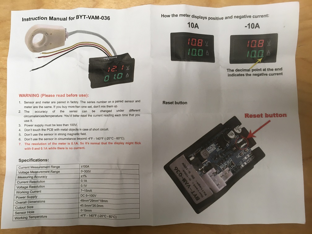
Once again, to save me the shipping costs, Paul purchased the meter for me and had it sent directly to me. Here are the instructions that came with it:
 And here is a photo of the meter that I received:

To install, connect the red and yellow wires together and to the “+” battery lead. Connect the black wire to the “-” battery lead. Then simply run one of the battery leads through the Hall-Effect sensor ring. If you get a negative reading on the meter, simply reverse the sensor ring.
Here’s a photo of the innards of the charger, after installing the meter:
 And here’s a photo of the charger in operation, with the new meter installed:
 Notice that the old meter (top left) shows a charging rate that is indistinguishable from zero, but the new meter shows that there is a fairly significant current of 2.1 amps. And it’s really nice to have a voltage readout. And, just as a test, I intentionally touched the battery charger leads together, and although the sparks flew, the smoke stayed in, and there was no damage to this new volt/ammeter.
I love this meter; I’m going to get some more of them and install them on some other chargers that I have.

looking for Carling switch on front of unit the switches 6 vdc to 12 vdc. any suggestions?
I believe that is a simple “Double Pole Double Throw Rocker Switch.” If y0u google that phrase, you will find multiple options. Please let me know if this works for you.
Tom