
Today I’d like to describe how to re-seal a Bosch VE Diesel Injection Pump. This particular one is of the type used on North American 1983 through 1986 Volvo 700-series (740 or 760) vehicles with D24T (2.4 liter Turbodiesel) engines. The same type of injection pump remained in use for several more years in other parts of the world.
There is a partial parts list, with part numbers and sources, at the very end of this post.
xxxxxxxxxxxxxxxxxxxxxxxxxxxxxxxxxxxxxxxxxxxxxxxxxxxxxxxxxxxxxxxxxxxxxxxxxxxxxxx
Temporary note, added 2/2/2017:
If you find the information in this post helpful, please take a look at the following post and see if you, or someone you know, can help me out.
xxxxxxxxxxxxxxxxxxxxxxxxxxxxxxxxxxxxxxxxxxxxxxxxxxxxxxxxxxxxxxxxxxxxxxxxxxxxxxx
Here’s a photo of the pump as I received it:
 Notice that the owner has removed the front mounting plate and the forward cold start thermostat housing.
Next we have something to watch out for:
 Notice that little special screw for the cold start cable? I found that in the bottom of the shipping box. This time we got lucky and I found the loose piece; next time we might not be as lucky. Please make sure that all the small components are securely fastened so they don’t get lost during shipment.
Next is a shot of some things *not* to send:
 That humongous mounting bracket, and the drive sprocket, are just excess weight. Please keep both of them and save the shipping costs. Both ways. However, if you feel you must send along the drive sprocket, that’s not terribly heavy, and it does have the advantage of my not having to go find a Woodruff key and a nut for my own use during the re-seal.
Next are a couple shots of the Volvo Special tool for locking the drive sprocket to the mounting bracket:

 And here’s a shot of the tool being used:
 Next are a couple shots of the Volvo special tool used for removing the drive sprocket:

 But, you don’t need that special tool to remove the drive sprocket. A chisel will do:
 Leave the nut a bit loose, give that chisel a whack, and the sprocket will come right off.
 Don’t lose the Woodruff key.
The same trick may be used to remove the front camshaft sprocket on D24 and D24T engines:
 Just loosen the screw a bit and give the screwdriver a whack; it’ll pop right off.
Next is a shot of the Volvo special tool for removing Injection Pump input shaft seals:
 There are other ways to remove the seal, but the special tool is the best, unless you’re re-sealing the whole pump, in which case it’s easier to pop the seal out with a screwdriver, as will be shown later.
Next we will remove the EGR switch mechanism from the top of the IP:
 Make note of where the 8mm hex head screws are located so you can put this switch back in its proper orientation later. From the marks it’s obvious that this one had been previously disturbed by someone else, before it was sent to me.
Actually, there are plenty of indications on this IP that it had been previously “rebuilt”, most likely by a “professional”, i.e., an authorized Bosch repair facility. Unfortunately for the owner of this pump, and for me, they didn’t do a particularly good job of re-assembling it. Mistakes were made, and damage was done, which I had to rectify.
Here’s a shot of the vacuum switch on this EGR mechanism:
 As can be seen, someone repaired this valve with a hose clamp, appropriately bent to hold it together. Looks like a decent job. I didn’t mess with it.
Next, remove the EGR mounting bracket:
 There are two 6mm Allen head screws to remove. The one shown above is short; the one on the other end, shown below, should be considerably longer.
 Unfortunately the above screw was too short, which caused damage to the IP, as will be shown later.
Next, remove the EGR switch drive ears, as shown below:

 Next, make note of the position of the “throttle” lever:
 Notice the scribe mark on the top of the 6mm throttle shaft. It is aligned with the most clockwise mark on the “throttle” lever. This will not always be the case; sometimes it aligns with one of the other scribe marks on the lever. You must make note of which lines match, and you must make sure that you put it back together in the same position.
Next, remove the 10mm hex nut, the lock washer, the spring, and the “throttle” lever:


 Notice that there is a washer between the IP and the “throttle” lever. Don’t forget to re-install it later. Also, make note of the position of the spring so you can be sure to re-install it properly.
Next, remove the microswitch that cuts out the EGR at idle:
 As you may notice from subsequent photos, I didn’t remove this microswitch until much later in the process. I should have removed it at this stage.
Next, remove the top cover of the IP:

 The two rear screws (above) are easy.
To remove the two forward screws, you will probably need to remove the idle screw and the fast idle screw:
First, the idle screw:

Just slightly loosen the jam nut, then remove the screw without disturbing the position of the nut, so you can put it back as close as possible to its former position.
Now take out the forward, inboard, IP cover screw:

Next, remove the fast idle screw:

Again, try to keep the jam nut in position so you can get this screw re-installed in its proper position.
Lay the two idle screws aside, making sure to keep track of which one goes where.

These two screws have their nuts in just about exactly the same position. That is not the general case; usually, the nuts will be in greatly different positions.
Now remove the forward, outboard IP cover screw:
 Notice the ball drive on the end of the Allen wrench. That makes removal of the two forward screws a lot easier.
Next, remove the fuel limiter screw:
 That’s a 13mm wrench. Again, try to move the jam nut as little as possible so you can put this screw back as close as possible to its original position.
Here’s a shot of the fuel limiter screw:
 Notice the washer and the o-ring.
Now, lift off the top cover:
 Push the “throttle” lever downward and out of the cover as you lift it off.
 The governor springs will stay behind as you lift the cover off:
 Here’s a shot of the under side of the top cover:
 And another shot of the governor springs:
 Align the notch on the shaft with the slot and slip the governor springs out:
 Don’t lose the little washer on the “throttle” shaft. Sometimes it sticks to the top cover, so take a look there, too.
Next, remove the cold start lever:
 But, before you take that 10mm hex nut off, make note of the position of the cold start lever, relative to the sheet metal stop:
 There should be just a little clearance between the lever and the sheet metal stop when the lever is rotated (gently) up against the internal mechanism of the IP.
Make note of the position of the spring and pick out the washer from the seal recess:
 Next, remove the sheet metal stop:

 Those screws that were holding the stop and the aluminum housing in place are both too short, and the threads in the aluminum IP housing are visibly damaged as a result. More on this later.
Remove the large black o-ring seal:

 Next, we remove what my Bosch dealer tells me is the pressure regulator valve:
 That special Bosch tool is rather hard to come by. Later, I will show you how to make a substitute, which, IMO, is even better than the official tool. You will need this special tool, or a good substitute, if you don’t want to do damage to the pressure regulator valve. So, buy one, or make one.
Here’s the regulator valve all taken out:
 Notice that there are 4 o-rings on it, 3 large ones, and one slightly smaller.
Next, remove the altitude compensation solenoid and the tube that connects it to the pressure regulator valve:

 Notice the spring adjustment shim in the aluminum housing. There are more on the other end of the spring. Make sure you put them all back in. And make sure that you have at least one shim on each end of the spring. Which end you put any additional shims on is not critical; the spring tension will be the same, either way.
Here’s a shot of the spring and shims:
 This particular pump had three shims on the inner end and one on the outer end. The number varies from pump to pump.
Now, remove the cast iron high pressure pump head:
 Make sure to loosen the screws uniformly so the head comes off squarely. It’s easy to break something here, although it’s far more likely to happen during reassembly than during removal.
 If you have to do some prying, do it gently:
 Here’s what the head looks like:
 Unfortunately, the photo is out of focus, but notice the washers and adjustment shims on the pins.
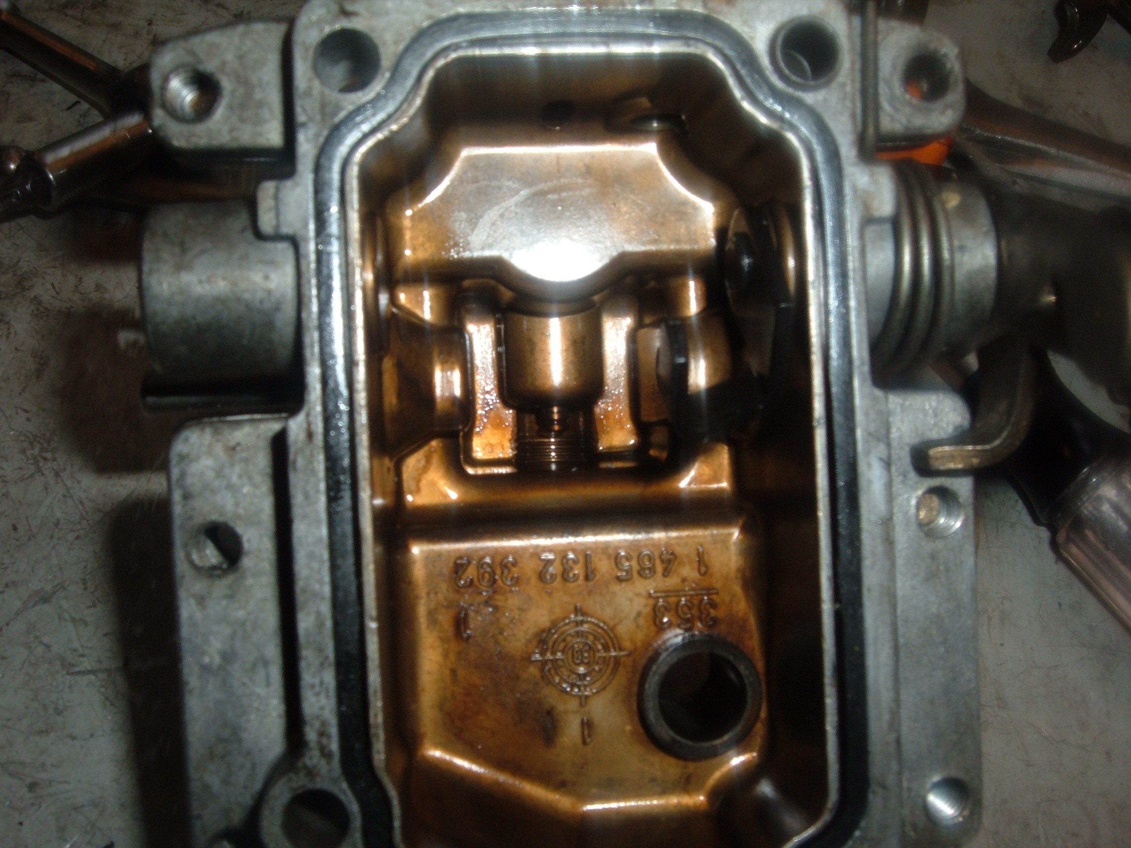
Here’s what the innards of this pump looked like after removal of the head:
 Yep, things fell all out of place. Fortunately, I know where they’re supposed to be; you may not have that advantage, so be careful.
More mis-located components:
 Another view:
 That roller belongs underneath the cam plate, not above it; it fell way out of position.
A close up of the cam plate:
 Don’t lose that little thrust washer.
Digging in a little deeper:
 Now we need to stand this pump up on its end, so let’s take a look at how to do that:
 The sprocket on the left is from this IP. The one on the right is from a Rabbit Diesel.
Another view:
 That Rabbit Diesel sprocket (on the right) makes a much better, and more stable, stand for working on these pumps. If you can get your hands on one, do so.
Here’s a shot of the Rabbit “stand” in use:
 Before we can go any deeper into this IP, we have to remove those triangular screws near the front. It takes a special tool:
 This is the official Bosch special tool. Later I’ll show you how to make your own, probably better, one.
Here’s the first screw, partially removed:
 And the second one:
 Notice that there appears to be no copper washer under the head of either screw. Copper washers were “standard” from the factory. At first, I thought there was no washer here at all, but later I discovered that there’s actually an aluminum washer here. Just another indication that this pump had been previously rebuilt.
I neglected to take a photo of the piece that is held in by those two special triangular screws, so here’s a shot of one from another pump:
 And another shot of the other side:
 Note that the tag says this piece is bent. That happened when someone (not me, I think) mis-assembled another pump. The ball got pushed out of place, and if I recall correctly, the high pressure pump got broken at the same time. It’s easy to do, so be mighty careful. I eventually straightened this piece out and have since used it in one of my own pumps.
More disassembly:
 Pick out the o-ring:
 Loosen the jam nut on the governor shaft:
 And remove the governor shaft:
 Here are the parts, all laid out:
 Notice the o-ring seal, and take note of where all the washers and spacers go. The exact location of the jam nut on the end of the governor shaft is not critical, but try to get it back somewhere close to where it was.
Next, remove the spring steel clip from the inside of the IP:
 That will expose the locking pin:
 Pull it out:
 Using a pick, pull the pin toward the center of the IP:
 And finish moving it with pliers:

 Now remove the hydraulic piston for the timing advance:
 Push the input shaft and roller carrier forward:
 And out of the pump:
 A closer view, showing the roller cage and governor drive gear:
 Here’s what’s behind that governor drive gear:
 If you’re certain that your low pressure pump is working and that the vanes are not stuck, then you don’t need to go any deeper into your pump. I did go deeper in this case, just to be sure.
 If you take any portion of that low pressure pump out, make sure you know which side to the parts go; you don’t want the pump casing to be in there backwards.
Here’s a shot of the governor drive gear:
 It’s held in place with a pair of rubber cogs, as shown in the next shot:
 These rubber cogs seem to last forever unless someone does something stupid to the pump, so you shouldn’t need to replace them. Sorry the photo is out of focus.
Using a screwdriver, pop out the input shaft seal:

 With the seal out, check the input shaft for wobble:
 Reinstall the low pressure pump:
 Hold the Woodruff key in place with a bit of assembly grease:
 And put the input shaft back in place, along with the roller cage, etc.:
 Next, get the pin lined up in the center of the pump casing hole, as shown to the right, below:
 Try to keep it there while you install the hydraulic piston for the timing advance:
 And push the pin down from the roller cage into the hydraulic piston:
 Next, install the locking pin:
 And the spring clip:

 Install a new o-ring on the governor shaft:
 Install the governor shaft and flyweights:
 Reinstall this little piece:
 Thinking that the copper washers were missing, I found some new ones:
 But I soon realized that there were already aluminum washers in place, so I didn’t use these copper ones.
The basic timing setting (#1 injection) for the Volvo D24 pump sprocket is shown next:
 Of course the above picture is taken with the Woodruff key in place.
But, this pump is easier to work on using the Rabbit sprocket for support:
 Secure it in place using the Woodruff key and the nut:
 Of course, with the Rabbit sprocket, #1 injection is with the mark on the sprocket aligned with the governor shaft at the top of the pump, as shown next:
 That locates the input shaft at this angle, as seen from the front of the IP:
 Put the cam rollers in place:
 Next, install the drive cog and the spring:
 Next, install the cam plate:

 Note that the drive pin points toward 1:00 o’clock, or the #1 injection line.
Put some assembly grease on the end of the high pressure pump piston:
 Make note of the notch (at 9:00 in the photo) that must be placed over the drive pin, located at #1 injection, and install that little thrust washer:
 Like this:
 Notice that the control collar has a chamfered edge toward the right (rear) side and a sharp edge (not shown) at the front. The hole in the face of the control collar goes toward the rear of the pump.
Here it, all in place:
 Put a new o-ring on the cast iron head:
 Add some assembly grease to the head:
 And insert the springs and pins:
 Put assembly grease between the adjustment shims to make sure they don’t fall off.
Tip it upside down and move it gently into place:
 Be very careful. This is where you have the greatest potential for destroying your IP. That high pressure pump is very easily broken during reassembly. If it doesn’t feel right, take it apart and try again.
 Now install a pair of screws into the head and torque it down uniformly. If you feel any resistance, you may be in danger of breaking the high pressure pump:
 Be very, very, careful.
Now, remove the manual shutoff lever:
 But before you remove that nut, make sure you know exactly what orientation to put it back together:
 Getting this back together in the right position is critical. If it’s not right, you will not be able to re-install the governor spring mechanism, and you run the risk of bending or even breaking it. If in doubt during reassembly, rotate that black (inner) piece one notch counterclockwise relative to the outer handle, as seen in the above picture.
Next, remove the washer and the o-ring:
 And install a new o-ring:
 Reinstall the handle and then remove the flat head screws:
 Punch out the dowel pin:
 No need to knock the dowel pin all the way out:
 You should see a small pin near the center of the next photo. That has to come out:
 But before I show you how to take that pin out, here’s what can happen if you don’t have the proper tools for the job:
 I made that mistake a couple of years earlier. Follow my advice, below, and make sure it doesn’t happen to you.
Here’s a shot of that piece we just took out:
 This is the point where I actually removed the idle position microswitch I mentioned earlier. So, here’s a shot of it, but you should take it out earlier and save yourself some grief:

It should be noted that the screw on the left of the photo is too short. I replaced it with one of proper length during reassembly.
Next, remove the plug, using a 5mm Allen wrench:
 This plug can be extremely difficult to remove. I’ve had several where the Allen hex stripped out and the plug stayed in place. You can’t apply heat here because of the rubber parts in the aneroid, so you need a better way. The next photo shows a ground-down file I made especially for the job:
 That file can be used to file flats on the plug to accept a 13mm open-end wrench. Fortunately, this plug came out fairly easily, as seen in the next photo:
 Nevertheless, I did file flats on the plug before re-installing it, for the next time, just in case. See below for more information.
Next, remove the pin:
 See those “screwdriver” slots? Well, you’d better have the proper “screwdriver” or you risk breaking the housing, as I showed you earlier. Here’s another shot, just to remind you:
 Next is a proper “screwdriver” for this job. I had a machinist make it for me:
 It’s made from a 7/16″ Grade 5 Allen screw, with a 3/8″ hex head on it.
Per commenter “Dan-C” request, machining dimensions for this “screwdriver” are as follows:
1. Nominal diameter of shank: 7/16″ (0.4375″)
2. Overall length, including head: 1.35″
3. Length without head: 0.92″
4. Major diameter of shank after machining (to fit inside threaded hole): 0.425″
5. Minor diameter of shank after machining (to fit inside screw slot): 0.345″
6. Length of minor (0.345″) diameter: 0.15″
7. Width (thickness) of screwdriver tip: 0.078″
8. Length of screwdriver tip: 0.07″
Here’s another view:
 The outside of this Allen screw has been burnished just a smidgen so that it will fit inside and pilot on the threads inside the hole for the plug, as shown next:
 Now pick out the o-ring:
 If this o-ring leaks, you can lose your prime such that your car won’t start, so it’s really important to replace it when re-sealing one of these turbodiesel injection pumps.
Here’s a shot of a special Bosch tool I bought to go beyond removal of this o-ring and take out parts down deeper in the hole: I’ve never had to use it. You probably won’t need one either.
Here’s what came out of the hole, along with a new (green) o-ring to put back in:
 Put the o-ring in and then re-install the “screw”, thusly:
 Tighten it down:
 Make sure you install the o-ring, then the “screw”, and tighten the screw, and only then, the pin. If you put the pin in before tightening the screw, it will pinch the od of the o-ring, and it will leak. BTDT. Now, put the pin in.
Next, I put the plug back in, tightened it snugly, and marked the bottom position with my file:
 Then, I took the plug back out, and filed two flats on it for a 13mm wrench. First one side:
 Then, the other:
 Note that I’m using a flat edge to sit the filed side down on to keep it parallel with the top of the vise.
It’s 13.14mm across the flats:
 A bit over 13mm, but all my 13mm wrenches fit it just fine. Tight, and that’s the way I like it:
 Next, install one of the flat-head screws:
 And drive the dowel pin in until it touches the flat-head screw:
 Finish the job with a punch:
 And install the second flat-head screw:
 Install a new o-ring on the “throttle” shaft:
 Next we have a special tool I had made for installing the governor springs and “throttle” shaft:
 The special tool is made from a piece of Delrin rod.
Here it is in use:
 Remember that manual shutoff lever I cautioned you about earlier? Well, here it is again, just to the right of that tube of sealant. If it’s not located at the proper angle, you will not be able to maneuver the governor springs past it as you re-install the top cover of the IP:
 So, save yourself a lot of grief, and potential breakage, and get that lever at the proper angle before you start.
New gaskets for the top cover are difficult to come by, so I use anerobic sealant to ensure no leakage. I tried Hylomar a few times, but the results were not satisfactory. The sealant I use is the same one that Volvo uses between the two halves of their later “White Block” cylinder heads. It’s Volvo Part Number 161059-9.
Here it is, applied to the two halves of the IP:
 Next, smear it out, nice and smooth, on each half of the split:
 Now, drop the top cover on, being careful to maneuver the governor springs past the manual shutoff lever without bending, or breaking, anything:
 Notice that the fuel limiter screw is very, very, loose so as not to interfere with reassembly.
Next, screw the cover down:
 This is about how much the manual shutoff lever should rotate:
 Put a new o-ring on the fuel limiter screw:
 And install it:
 Don’t forget to tighten the jam nut:
 Put new o-rings on the pressure regulator valve:
 It takes three of one size and one of the other. First one off, last one back on:
 I just finished putting the last one back on.
The cold-start mechanism and its o-rings:
 Note the two different lengths of screws in the next picture:
 It had two of the short ones in it; it should have had the longer ones. The short ones did damage to the threads, especially at the upper hole. I had to repair the threads.
The thread damage is quite visible in the next photo:
 First I tried cleaning up the threads with a tap and installing a proper length screw:

 But that didn’t work; the longer screw stripped out, also:
 So, I had to install a Helicoil:
 I drilled it out by hand to minimize the possibility of drilling too deeply:
 Then I installed a Helicoil:
 In the next photo, notice the installation tab that is yet to be removed, and also notice the damage to the o-ring seat:
 Break out the installation tab:

 I put in a small dab of epoxy. I don’t know if it did any good, but it made me feel better:
 Installing the cold-start mechanism:
 Installing the timing advance hydraulic cylinder cover:

 Installing the timing advance hydraulic cylinder spring:
 Installing the pressure regulator valve:

 Back to the cold-start mechanism:


 Make sure there’s the proper amount of clearance between the lever and the sheet metal stop.
Lubricate the input shaft seal before installing it:
 Drive it home with a socket:

 More mistakes previously made, almost certainly by an authorized Bosch rebuilder:
 These screws are too short. They should have been as shown in the next photo:
 I installed the ones at the right of the above photo.
More previous mistakes:
 The screw on the left goes into steel and is correct. The one on the right goes into aluminum and is too short. It caused damage to the pump housing.
Another shot of the same bracket, and the left screw:
 That left screw is okay because it goes into a steel bracket.
But, the right one, well, that damaged the pump housing as shown below:
 I had to repair that hole with a Helicoil, also.
Once again, I drilled it out by hand:
 Installing the Helicoil:

 Knocking out the installation tab with a punch:
 Here’s another threaded hole that was pretty well damaged:

I installed a Helicoil in that hole, also. This time, because I needed a tool longer than my “jobbers” bit, I used a 1/4″ reamer to “drill” out the hole:
 And with some small sockets and adapters, I was able to tap the hole for a Helicoil:
 Installing the Helicoil:
 Just enough room, with none to spare.
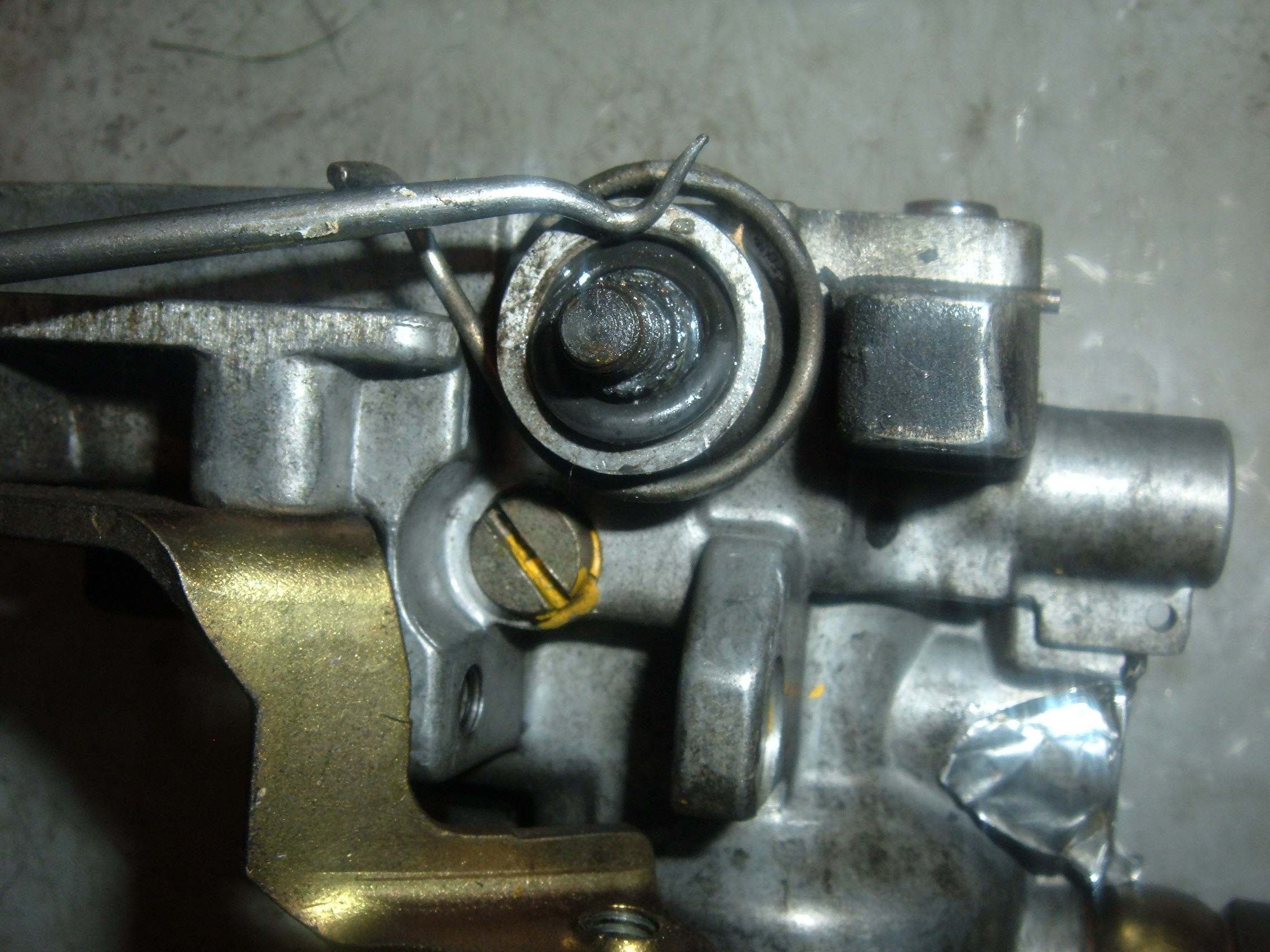
Next, install the “throttle” lever, making sure to align the marks properly:
 Install the EGR switch drive “ears”:
 Pay careful attention to corrosion and other marks on the lever to ensure proper orientation of the ears. Of course, the EGR probably doesn’t work anyway, and there are ways to adjust it in the field, but not many people have the instructions.
Install the bracket:
 And the EGR switch:
 Use the markings to get that switch right back where it used to be:
 In the next photo, the short screw is what was in this IP. The longer screw is what should have been there:
 This hole now has a Helicoil in it because of damage caused by the short screw.
The proper screw length is 16mm:
 The short one is only 10mm long.
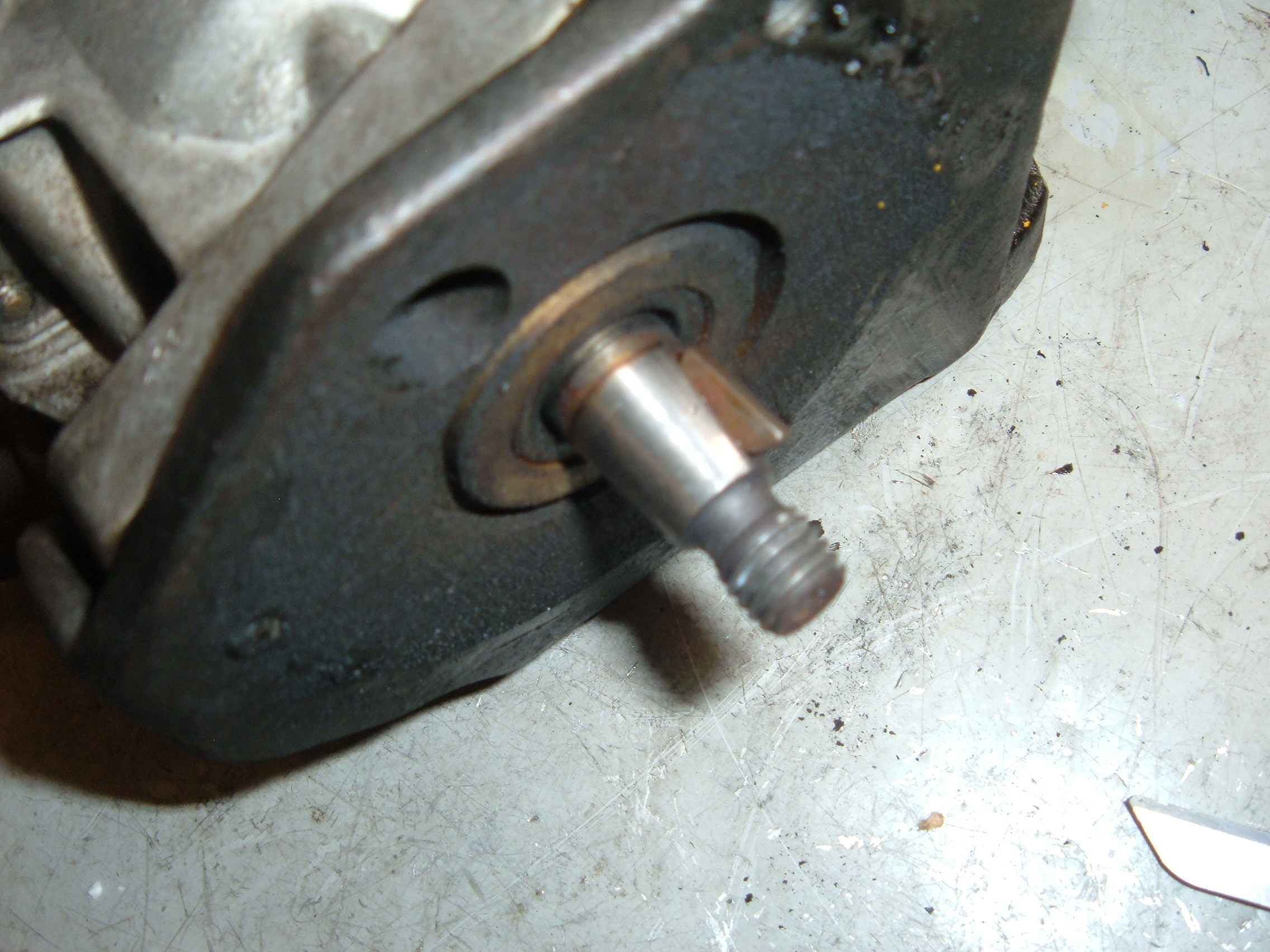
Now we get to the Cold Start Thermostat. This pump came to me without one on it, and it went home without one, but for the sake of completeness, I went through the motions and took photos anyway:
 The above shows a cold start thermostat and my special tool for R&R. I made the tool from an 18mm Craftsman impact socket.
Here’s a shot of the thermostat, all removed, showing the o-ring seal:
 And here’s a picture of a pair of new thermostats, one from Volvo, the other from Bosch:
 Next, my “special tool” for installing the thermostat housing:
 Install the long screw in the top screw hole, crank it down, then install the bottom screw:
 Since this is going back to the owner without a cold start thermostat, or a front mounting plate, I took that stuff back off:
 Next, we replace the front o-ring seal, using my special tool that I made from a 24mm impact socket:
 The tool was made by grinding away, on three of the sides, with my Dremel tool, just as I will soon show you for the 12mm variety.
The plug, the o-ring, and the tool are shown below:
 This is the first, and so far, only IP that I’ve replaced this o-ring on. I’ve never known one to leak, and it can be easily replaced in the field, without removing the IP from the vehicle, if it ever does leak, so I recommend you leave yours alone.
Next, we go after the o-ring seal on the fuel shutoff solenoid:


 This is also the first of these o-rings that I’ve ever replaced, and once again, I recommend that you leave yours alone unless you have a problem with it.
Next, the altitude compensation solenoid:

 I’ve also never replaced one of these o-rings before, and I recommend you don’t either.
Next I discuss the screw that holds the rear timing belt cover to the IP mounting bracket:
 See that 6mm screw coming in at the top, from the right? Life is considerably easier, on both D24 and D24T engines, if that screw, or a similar one, comes in from the left, instead.
You need one about 20mm long, as shown next:
 And you need a nut, and when you’re done, it’ll look sort of like this:

With this configuration, it’s much easier to remove and re-install that rear timing belt cover. Try it, you’ll see.
As a reminder, here’s another look at a top cover and its gasket: And here are three gaskets:
 The gasket in the middle is an original one from one of these IPs. The ones on the left and on the right are what come in repair kits these days. The one on the left will not fit because of the nubs on it. The one on the right seems flimsy, and I’ve never used one of them, although my Bosch dealer assures me that work just fine.
I have successfully used ones like the one on the left by removing the nubs with a razor blade.
But, being a certified CB, I prefer to use the one in the middle, along with a bit of anerobic sealant to make sure it doesn’t leak. So far, the results have been great.
Here’s what the flimsy (right) one looks like installed in the top cover:
 Notice how it doesn’t fill the space very well.
And next is what the one on the left looks like on the cover:
 It will not fit into the grooves unless you shave the nubs off.
Remember those “triangular” screws for which I promised earlier that I’d show you how to make a special tool? Well, here we go:
 I bought a 3/8″ drive 12mm impact socket from NAPA. Had to special order it. I later found them in stock at my local Lowes Store.
I ground out three of the sides using my Dremel tool: I used the small, tapered blue stone for this job. I used that larger stone (in the caliper) to make the 24mm variety I mentioned earlier.
This home-made tool, with a 3/8″ female socket drive, is considerably more convenient than the official Bosch one, which has a 1/2″ male drive, as shown in the next photo:
 I also promised to show you how to make a special tool for the pressure regulator valve:
 For this, I purchased a special 10mm square female socket via the Internet. It’s a CTAT-2048, and it fits certain Ford, BMW, and Toyota drain plugs:
 Once again, I removed a bit of material using my trusty Dremel tool and the special chainsaw grindstone shown above. This homemade tool is also considerably easier to use than the official Bosch tool, which has a 1/2″ male square drive, as shown in the photo above. The tool in the middle of the top row has been hollowed out to fit onto the oblong screw head of the pressure regulator valve, seen just to its right in the top row.
Now, we move on to the inlet and outlet banjo bolt fittings for the IP:
 The one on the left is obviously for the outlet. The unmarked one on the right is for the inlet. Don’t mix them up. Bad things happen if you do.
As seen in the next photo, the outlet banjo bolt has a tiny orifice that serves as a restriction to the flow and causes the pressure inside the IP to increase with engine RPM:
 You do not want to restrict the inlet flow, and you do want to restrict the outlet flow.
As seen in the next photo, the outlet banjo bolt has a strainer inside it:
 The strainer should keep that small orifice from plugging. We hope.
As seen in the next photo, the IP will almost fiteasily inside a USPS Flat Rate Box:
 Unfortunately, the “throttle” lever sticks outside the box, as seen next:
 However, if you want to ship me a pump for rebuild, and if you’d like to do it cheaply, you could remove that lever, taking care to note which of the scribe lines must match up, then re-install the lever arm yourself after I ship it back to you. Your call.
But, make sure you ship me the lever so I can have it to work with. Here’s a partial parts list. The list is sorted by Description, and there are optional part numbers, and sources, for several of the items.
| Part No. | Description | 240 | 700 | Cost | Source |
| DGK126 | Inj Pump Seal Kit, D24 (Shaft Seal too Large) | 1 | 10.65 | Bosch | |
| DGK121 | Inj Pump Seal Kit, D24T (Shaft Seal too Large) | 1 | 1 | 16.92 | Bosch |
| 1-460-210-306 | O-Ring, 2.5mm x 22mm ID, for Inj Pump Cold Start Thermostat | 1 | 1 | 2.07 | Bosch |
| 2-460-210-012 | O-Ring, for Inj Pump front end, 2.5mm x 67.56mm od (2.66″ od) | 1 | 1 | 4.05 | Bosch |
| 2-460-223-001 | O-Ring, Green, 32mm od, for Inj Pump Cold Start & Timing Adv. | 3 | 3 | 2.25 | Bosch |
| 1-460-210-347 | O-Ring, Viton, 1.5mm x 4mm ID (for TD Inj Pump Top Boost Rod) | 1 | 0.63 | Bosch | |
| 1-460-210-301 | O-Ring, Viton, 2.5mm x 10mm ID (for Inj Pump Cold Start Shaft & Shutoff Lever) | 2 | 2 | 1.98 | Bosch |
| MSC-31959059 | O-Ring, Viton, 2.5mm x 10mm ID (for Inj Pump Cold Start Shaft & Shutoff Lever) | 2 | 2 | 0.63 | MSC |
| 1-460-210-349 | O-Ring, Viton, 2.5mm x 18mm ID (for Front IP Plug) | 1 | 1 | 3.21 | Bosch |
| 1-460-210-006 | O-Ring, Viton, 2.5mm x 9mm ID (for Inj Pump Shutoff Solenoid) | 1 | 1 | 2.25 | Bosch |
| 1-460-225-082 | O-Ring, Viton, 2mm x 10mm ID (for Inj Pump Press Reg Vlv) | 3 | 3 | 2.84 | Bosch |
| MSC-31958937 | O-Ring, Viton, 2mm x 10mm ID (for Inj Pump Press Reg Vlv) | 3 | 3 | 0.76 | MSC |
| MSC-31958887 | O-Ring, Viton, 2mm x 5mm ID (for Inj Pump Fuel Adj Screw) | 1 | 1 | 0.34 | MSC |
| 1-460-210-008 | O-Ring, Viton, 2mm x 6mm ID (for Inj Pump Throttle Shaft) | 1 | 1 | 1.98 | Bosch |
| MSC-31958895 | O-Ring, Viton, 2mm x 6mm ID (for Inj Pump Throttle Shaft) | 1 | 1 | 0.44 | MSC |
| 1-460-225-081 | O-Ring, Viton, 2mm x 8mm ID (for Inj Pump Press Reg Vlv & Governor Shaft) | 2 | 2 | 0.76 | Bosch |
| MSC-31958911 | O-Ring, Viton, 2mm x 8mm ID (for Inj Pump Press Reg Vlv & Governor Shaft) | 2 | 2 | 0.71 | MSC |
| 1-463-412-301 | Screw, 4mm Cheesehead (for Inj Pump Cold Start) | 1 | 1 | 4.46 | Bosch |
| 1-460-105-311 | Seal Ring, Metal Washer (for TD Inj Pump Top Boost Rod) | 1 | 1.58 | Bosch | |
| 844178 | Seal, Injection Pump Input Shaft | 1 | 1 | 10.59 | Volvo |
| 1-460-283-312 | Seal, Injection Pump Input Shaft | 1 | 1 | 13.77 | Bosch |
| 9139507 | Thermostat, Cold Start, Inj Pump | 1 | 1 | 82.17 | Volvo |
| 1-467-202-302 | Thermostat, Cold Start, Inj Pump | 1 | 1 | 76.00 | Bosch |
| 1-463-123-576 | Tie Rod, Inj Pump Cold Start | 1 | 1 | 14.03 | Bosch |
Sorry about the poor formatting. The list is copied from an Excel spreadsheet, and I don’t seem to have any control over the formatting.

hi i have this pump on my 940 tdi year 1995 . i have fitted a cold start device second hand one i found not remove the old wax stat i made a slotted screwdriver to fit into the wax stat slot but no way could i turn it do is it better if i put it in very hot water first i take it is a anti clockwise to undo this wax stat i twisted my home made screwdriver any thoughts . your bulletin is excellent
regards jim
Hot water might help, but I can’t guarantee it. All you can do is try. You might also try heating it with a propane torch. But be aware that there is a rubber o-ring down there, and if you overheat it, you will have to replace it. No big deal; it should be readily available.
The best approach would be to make one of those special tools that I show in my post, but that could cost you a pretty penny.
If you don’t want to go whole hog and make one from a socket, as I show in the post, then you might try something I did many years ago: I got a large, thick, heavy washer and ground it down to fit into the slots and turned it with a pair of Vise-Grips. Also, you can easily remove the pin from the center of the thermostat, then deal with the slotted “nut”, and then replace the pin after it’s all back together. There is absolutely zero harm that you can do by removing that pin; just keep the dirt out of it.
You just convinced me to not try to do this on my own. How much do you charge for a rebuild of a volvo d24?
At this time, my price is $200.00 plus return shipping. If it needs a cold start thermostat, then the price goes up by another $100.00.
Hello Tom Bryant !
Nice work and pictures!
Have a question about a leak related to air-inlet boost pressure kompensator.
Take a look at PDF-file sida 51 and 52. ( http://www.cnctechnw.com/PDF/BoschDistPump.pdf )
Sid 51 pos10 “Vent” is related to the leak
At the part list, Bosch part # 1-460-210-347, is this o-ring relevant to a “vent-leak”
My Q: will the part# 1-460-xxx o-ring stopp the leak related to pos10 above ?
My next Q your text/pic; -“See those “screwdriver” slots? Well, you’d better have the proper “screwdriver” or you risk breaking the housing, as I showed you earlier. Here’s another shot, just to remind you:”
is it possible to ask about a skiss ok put digits in part of inch (1inch = 25.4mm?)
Regards from Sweden city Goteborg and tomorow, 19/6-15, is Midsummer.
Dan-C
Dan,
Yes, leakage at the vent (10) is often caused by a bad o-ring, Bosch P/N 1-460-210-347. Replacing that seal should stop leakage from the vent, unless there is a defect in one of the associated metal sealing washers, which are extremely unlikely to be bad; I’ve never seen one of those go bad. To get at those metal sealing washers, you would need the special Bosch (Flag) tool, which I have never had to use, but is shown and discussed in the text of my post.
I have revised my post to include machining dimensions for my special homemade “screwdriver.”
Tom
Hello Tom,
Are you still rebuilding these injection pumps? And if so how do I get your address and set up a time with you to get it done
Questions of this nature should discussed via e-mail. My contact information may be found on the “About” page.
Tom
Hey Tom
I have the same pump in my 1991 lt 45
Turbo 2.4
Wouldn’t happen to know the final setting for it would you?
Pump was sent off for a rebuild // leaking like crazy
I’ve seen on line .80 or .85 even .95
Can’t seem to find an answer
Best regards
Jeremiah Woods
Jeremiah,
I’m sorry, but I do not have access to the timing specification for your 1991 LT; I have specifications only for certain Volvo models. What I can tell you is that, for Volvos, the nominal timing specs range from 0.70mm to 0.90mm, with a minimum allowable of 0.65mm and a maximum allowable of 0.95mm. I always set the timing on Volvos at 0.85mm, regardless of what the exact specification is for the particular model. I would assume that the LT should be set somewhere near the same 0.85mm value.
I believe that the primary reason for different timing specifications is that the compression ratios vary somewhat. A secondary reason is that certain markets (most notably California) had slightly retarded timing specifications, probably for emission reasons.
Yes, I know, Volvo advertises a compression ratio of 23:1 for all their D24 and D24T engines. But, that isn’t all that accurate, and the actual values vary. The variations in the North American market are greater, I believe, than in the rest of the world. This is because the early 1979-1981 D24 engines used a larger (32mm) swirl chamber, whereas the later 1982 and follow North American D24 and D24T engines used a smaller (30mm) swirl chamber. However, the same 32mm size swirl chamber continued to be used in Europe, and probably in the rest of the world. Thus, it would be reasonable to assume that your LT might benefit from not having overly-advanced timing. This would be particularly advisable if your head gasket is on the thick side, which, unfortunately, was the usual case when these engines left the factory. Thick head gaskets decrease the actual compression ratio and increase the tendency for combustion knock.
For one particular 32mm D24 engine, I measured the actual compression ratio at 23.83:1, whereas for a later 30mm D24T engine, I measured the actual compression ratio at 25.06:1. It’s not a huge difference, but it’s enough to have a significant effect on combustion knock if the timing is too advanced for those early engines. Those early D24 engines have a timing specification of 0.70mm. Whereas the later D24T engines generally have a specification of 0.85mm (minimum of 0.72mm and maximum of 0.95mm).
I would recommend trying the “usual” specification of 0.85mm. If you find that there is significant combustion knock, you could either retard the timing a bit, or you could do what I would do, which is to install a thinner head gasket. And, if there is no objectionable combustion knock, you might try a slightly more advanced timing of 0.90mm or so and see how that works for you.
Tom
Thank you so much,
You have no idea how your reply has changed my thoughts on this lt 45
The D24T was extreamly hard to start in the winter, your comment about the head gasket makes it all crystal clear now.
Next fall ill give it a rebuild
The pump arrived today ….. I will keep you in mind while I’m reinstalling & timing….
I owe you a case of beer or something…
Many blessings.
Jeremiah Woods.
Jeremiah,
Headgaskets make a significant difference to winter starting, but glow plugs and general engine condition are much more important. Thinner headgaskets also make a dramatic improvement to horsepower and performance. If you do decide to replace your headgasket, you should try for the thinnest one you can get away with. That means that you really must use an MLS headgasket, as you cannot readily predict, or control, just how thick a composition headgasket will be.
Volvo’s original “Green Book” specifications, when boiled down to their basics, call for a piston to cylinder head clearance in the range of 0.58-0.73mm (0.0228-0.0287″). That is an overly-conservative specification. And to make matters worse, engines often left the factory with piston to head clearances well in excess of the maximum specification. I have seen situations where a 3-notch gasket was used when the clearance specifications should have dictated a 1-notch gasket.
Then, to make matters much, much, worse, aftermarket replacement pistons are often about 0.25mm (0.01″) shorter than the OEM pistons, so if they’re used with the original head gasket thickness, the situation goes from bad to intolerable.
The cure is to install the thinnest MLS head gasket you can. I have experimented with many, many, such thinner head gaskets to find out just how small a piston to head clearance I can get away with. The answer is just about 0.014″ (0.356mm). I have had several successful engines with that low of a calculated clearance. And, I’ve also had a few failures with that same calculated clearance. To be safe, I don’t really recommend trying to go below a minimum piston to head clearance of 0.017″ (0.432mm).
To achieve such low clearances, it is generally necessary to remove layers from an MLS head gasket. Such gaskets have 4 layers. You can get away with removing any of those 4 layers *except* for the top layer. You can also get away with using a bottom layer in place of the top layer, but you have to put a sealant on the bare metal side of that layer, which would then face upward toward the cylinder head. I recommend Volvo’s “High Temperature Chemical Gasket” Part Number 1161059-9 for that purpose.
If you decide to go with one of these radically thinner head gaskets, you must measure your piston deck heights very accurately, and you must make sure the piston top is square across (or level). And, you will have to measure the thicknesses of each layer of your MLS head gasket very carefully.
For reference purposes, here are the layer thicknesses that I have measured on Volvo’s MLS head gaskets (which, unfortunately, are no longer available):
Top layer: 0.23mm
2nd layer: 0.87, 0.92, 0.97mm (1, 2, & 3 notch gaskets, respectively)
3rd layer: 0.12mm
Bot layer: 0.23mm
As just one example of how a person can mix and match head gasket layers to obtain a desired thickness, here’s what I used for my latest head gasket replacement: One top layer, and 4 bottom layers. That’s right, I didn’t use the thick “notched” layer at all. The piston deck heights maxed out at 0.030″ (0.762mm), and I needed a thin head gasket, so I used only the corrugated “top” and “bottom” layers. I had several brand new bottom layers that had been removed from previously-installed gaskets. So, I combined four of those bottom layers with one previously-used top layer that had lost its rubber coating. I applied a bit of that special Volvo anerobic gasket maker to both sides of that top layer. The calculated piston to head clearance of this gasket is 0.0153″. It was installed in the engine on 6/24/2015, and to this date (4/30/2016) has accumulated over 7600 trouble-free miles.
Be extremely careful with your measurements, and don’t push the envelope too far until you’re really sure of yourself.
If you do this, and depending on just how thick your old gasket was, you may notice a dramatic improvement in horsepower and performance.
Tom
Pingback: Bosch Model EFEP 515 Fuel Injection Pump Test Bench | Tom Bryant, Wiscasset, Maine
What about the internal settings how do you do advance ,transfer pressure , max fuel etc ..
Hopefully when you sort your Bench out in regards Test pipe Size and test Injectors and that will include orifice plate as well . plus all the Test plans .
Norm
All in good time. Rome wasn’t built in a day. Ultimately, I will be able to do the rest of the stuff. Meanwhile, I’ve re-sealed dozens of these pumps, and they’re all working just fine. Every single one of them.
Tom
hi Tom, I’ve just changed the front o-ring from the plug, in situ, and now after several times of trying to start the engine…nothing happens…can you help?
I have a Land Rover Discsovery 300 tdi, 1997.
I recently change the lift pump and the cast iron o-ring…but now it doesn’t want to start…
Do I need to do something special?? Any special way of prime it…
best,
ricardo
Ricardo,
I suspect that this will require too much correspondence to properly cover via this blog. Please contact me directly via e-mail at thosbryant@gmail.com so we can discuss the issues in detail.
Tom
Beautiful write-up about our beloved d24/d24t engines` “sensitive” pumps. Many thanks for sharing your priceless knowledge!
a member of http://www.d24t.com – The Volvo Diesel Forum